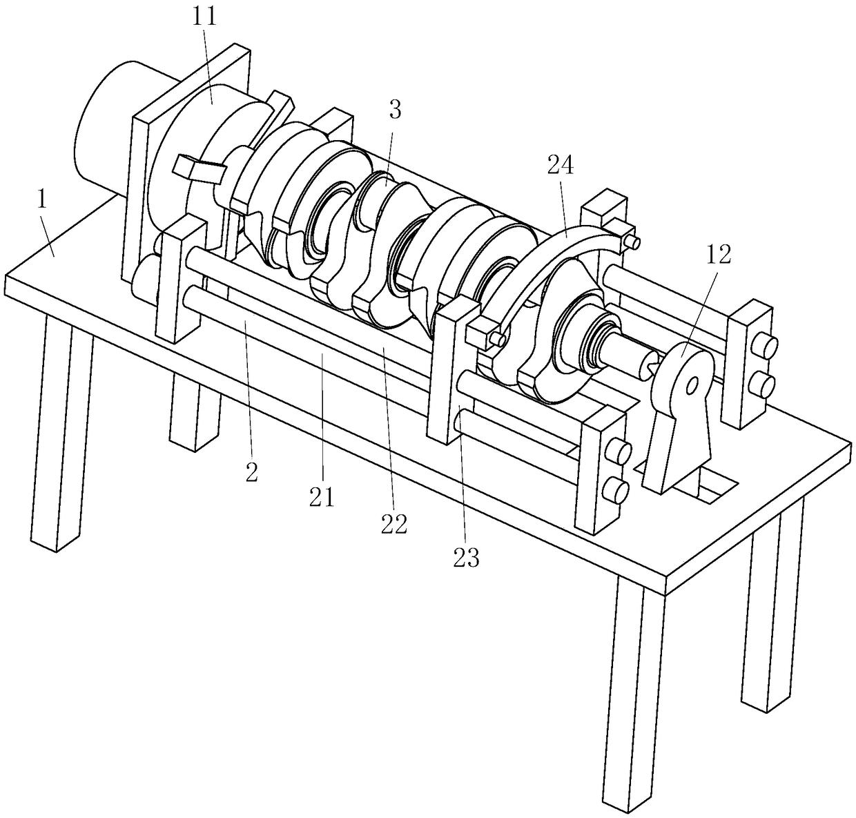
Electro-brush plating repairing machine tool for automobile engine crankshaft

An automobile engine and electric brush plating technology, applied in the direction of electrodes, electrolysis process, electrolysis components, etc., can solve the problems affecting the whole machine work, uneven brush plating, low efficiency, etc., to improve repair efficiency, improve brush plating efficiency, The effect of shortening the drying process

Active Publication Date: 2018-12-07
浙江唯诺卫浴股份有限公司
View PDF3 Cites 2 Cited by
  • Summary
  • Abstract
  • Description
  • Claims
  • Application Information

AI Technical Summary

Problems solved by technology

[0003] The crankshaft is a precise and expensive important part that can withstand alternating loads and high mechanical strength. Once a certain part of the crankshaft is damaged, it will seriously affect the work of the whole machine
The damage of the connecting rod neck of the crankshaft is one of the common damages. At present, the commonly used remanufacturing and repair methods for the damage of the connecting rod neck of the crankshaft include electric brush plating, spraying, and electric welding surfacing. Among them, in the brush plating method, manual brushing is used. The efficiency of plating is low. At the same time, due to the eccentricity of the connecting rod neck relative to the central axis of the crankshaft, when it is clamped on the lathe for brush plating, the brush plating is uneven, which affects the repair efficiency of the connecting rod neck.

Method used


Image

  • Electro-brush plating repairing machine tool for automobile engine crankshaft
  • Electro-brush plating repairing machine tool for automobile engine crankshaft
  • Electro-brush plating repairing machine tool for automobile engine crankshaft

Examples


Embodiment approach

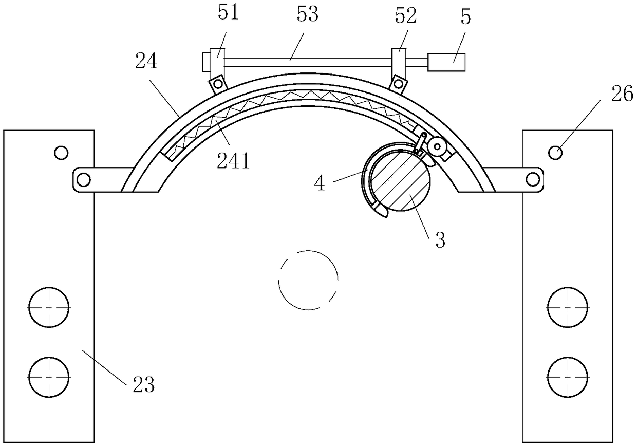
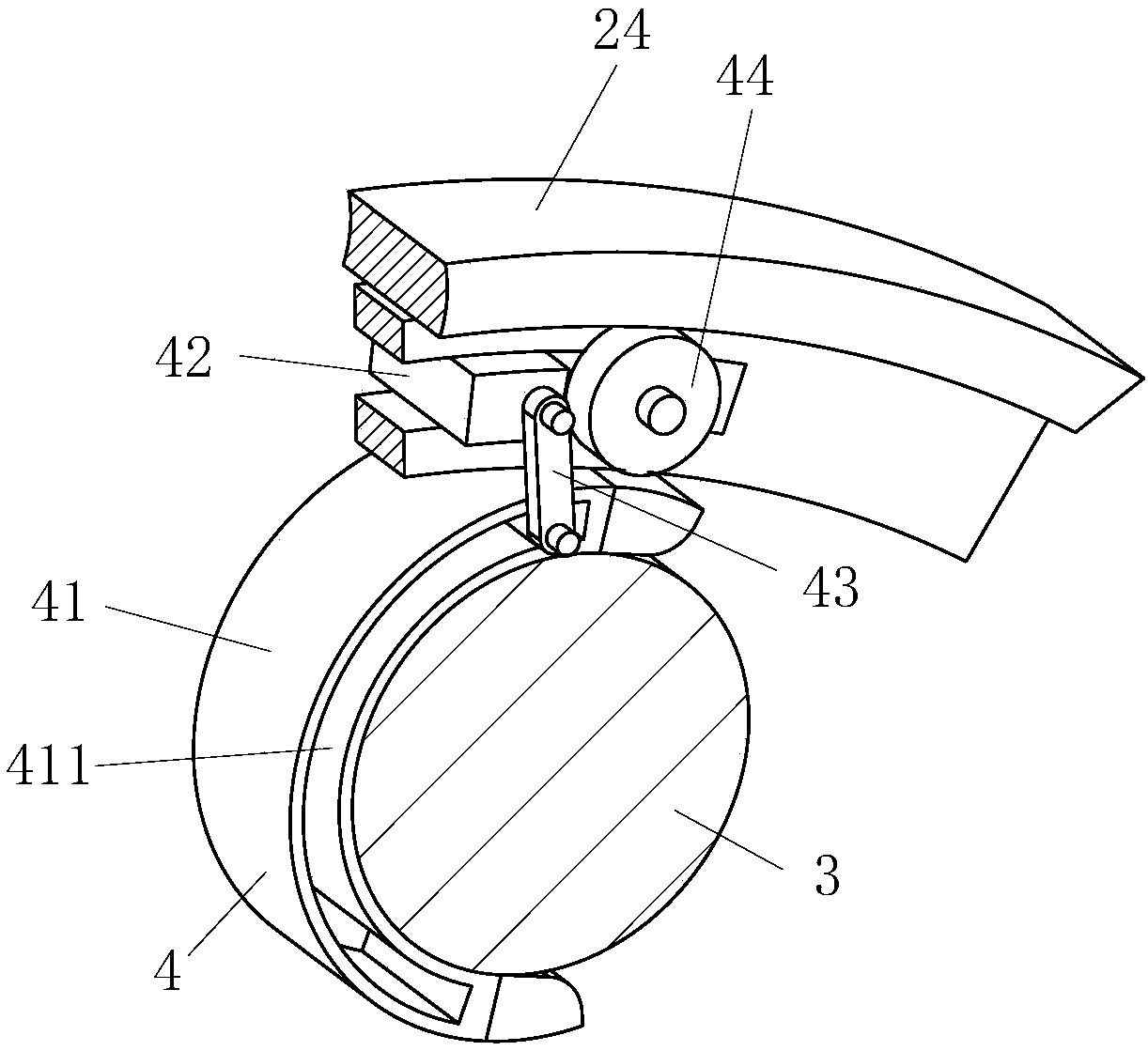
[0023] As an embodiment of the present invention, the brush plating device 4 includes a brush ring 41, a second slider 42, a support plate 43 and a gear 44; the brush ring 41 is semicircular; the brush ring 41 The inner ring is provided with hair bundles; the brush ring 41 is provided with a through first chute 411, and the arc plate 24 is provided with a second chute 241, and a second slider is slidably installed in the second chute 241 42, the second slider 42 is connected to one end of the second chute 241 through a spring; a support plate 43 is provided on both sides of the second slider 42; a sliding installation is provided between the two support plates 43 on the first chute 411 The inner roller shaft; one side of the support plate 43 is provided with a gear 44 that is rotatably installed on the second slider 42; groove; the outer ring of the brush ring 41 is provided with a tooth groove meshing with the gear 44; when the second slider 42 slides along the arc plate 24, ...


PUM


Abstract

The invention belongs to the technical field of crankshaft repairing, in particular to an electro-brush plating repairing machine tool for an automobile engine crankshaft. The electro-brush plating repairing machine tool comprises a workbench, a chuck, a tailstock, a sliding mechanism and an electro-brush plating device. The tailstock and the chuck are coaxially arranged on the workbench. The sliding mechanism comprises a lead screw, a guide column and first sliding blocks. The lead screw and the guide column are parallel to the axis of the chuck, the lead screw and the guide column are provided with the first sliding blocks, and an arc-shaped plate is arranged between the two first sliding blocks. An inner ring of the arc-shaped plate is tangent to a rotary connecting rod neck in an interval manner. The inner ring of the arc-shaped plate is provided with the electro-brush plating device. The electro-brush plating device comprises a brush ring, a second sliding block, supporting platesand a gear. Due to the fact that the electro-brush plating repairing machine tool is provided with the brush ring, when the connecting rod neck eccentrically rotates, the connecting rod neck is clamped into the brush ring, along with rotation of the crankshaft, the second sliding block is pushed to slide along the arc-shaped plate, when the second sliding block slides, the gear drives the brush ring to rotate around an outer ring of the connecting rod neck and carry out uniform brushing electric plating on the outer ring of the connecting rod neck, and the repairing efficiency of the crankshaft is improved.

Description

technical field [0001] The invention belongs to the technical field of crankshaft repair, in particular to a brush-plating repair machine tool for an automobile engine crankshaft. Background technique [0002] The crankshaft is the main rotating part of the engine. After the connecting rod is installed, it can undertake the up and down (reciprocating) motion of the connecting rod into a circular (rotating) motion. It is an important part of the engine. Its material is made of carbon structural steel or ductile iron. There are two important parts: the main journal, the connecting rod journal, (and others). The main journal is installed on the cylinder block, the connecting rod journal is connected with the large end hole of the connecting rod, and the small end hole of the connecting rod is connected with the cylinder piston, which is a typical slider crank mechanism. The lubrication of the crankshaft mainly refers to the lubrication of the big end bearing bush of the connec...

Claims


Application Information

Patent Timeline
Patent Type & Authority Applications(China)
IPC IPC(8): C25D17/00C25D5/06C25D17/12
CPCC25D5/06C25D17/00C25D17/12
Inventor 王志伟
Owner 浙江唯诺卫浴股份有限公司
Why Eureka
Try Eureka