
Auxiliary device for cantilever construction of steel box girder

An auxiliary equipment, steel box girder technology, applied in bridge construction, bridges, erection/assembly of bridges, etc., can solve problems such as increased cost, cumbersome cable tensioning process, long construction period and cost, etc., and achieves reduction of vertical deformation. , Good technical and economic benefits, simple disassembly effect

Pending Publication Date: 2018-12-07
TSINGHUA UNIV
View PDF0 Cites 0 Cited by
  • Summary
  • Abstract
  • Description
  • Claims
  • Application Information

AI Technical Summary

Problems solved by technology

However, the erection of temporary cable towers requires a lot of construction time and cost, and the tensioning process of the cables is cumbersome. After the construction is completed, the temporary cable towers must be removed, which increases the construction cost.

Method used


Image

  • Auxiliary device for cantilever construction of steel box girder
  • Auxiliary device for cantilever construction of steel box girder
  • Auxiliary device for cantilever construction of steel box girder

Examples


Embodiment Construction

[0024] Embodiments of the present invention are described in detail below, and examples of the embodiments are shown in the drawings, wherein the same or similar reference numerals denote the same or similar elements or elements having the same or similar functions throughout. The embodiments described below by referring to the figures are exemplary and are intended to explain the present invention and should not be construed as limiting the present invention.

[0025] Auxiliary equipment for cantilevered construction of steel box girders according to an embodiment of the present invention will be described below with reference to the accompanying drawings.

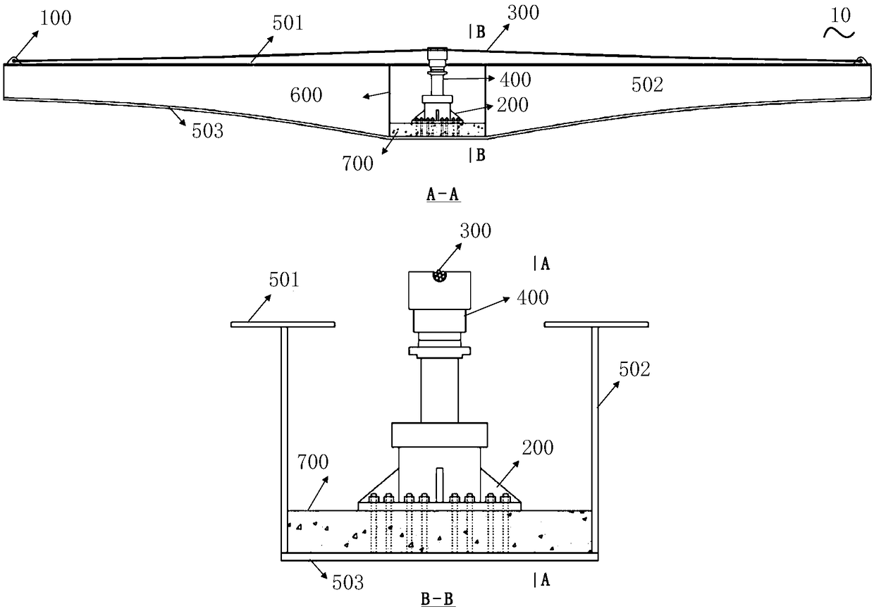
[0026] figure 2 It is a structural schematic diagram of auxiliary equipment for cantilever construction of steel box girders according to an embodiment of the present invention.

[0027] Such as figure 2 As shown, the auxiliary equipment 10 for cantilevered steel box girder construction includes: a connecting ear plat...


PUM


Abstract

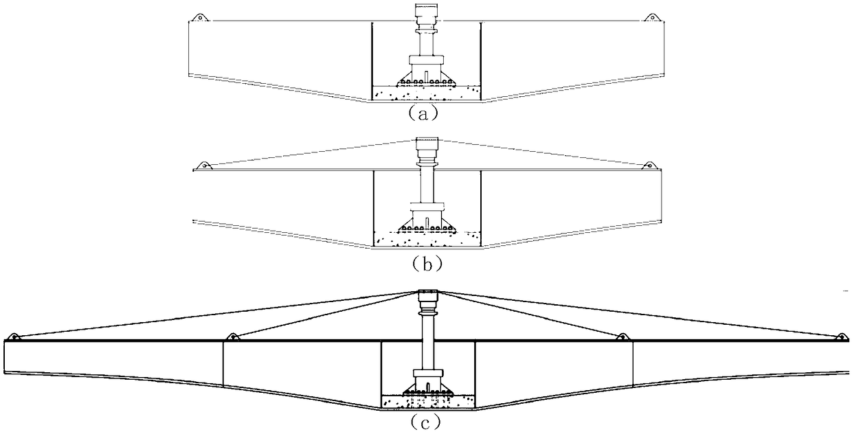
The invention discloses an auxiliary device for cantilever construction of a steel box girder, which comprises a connecting lug plate and a fixing device; at least one wire rope for providing additional stiffness to the steel beam; a jacking device, a jacking device is installed in that support segment of the steel box gird through a fixing device, so as to connect both ends of the wire rope withthe cantilever ends of the steel box girder respectively through a connecting structure after the steel girder is suspended to a preset length, and the middle section of the wire rope is restrained ina clamping groove of the top end of the jacking device to adjust the tension of at least one wire rope by controlling the height of the jacking device. the auxiliary equipment can effectively reducethe stress level of the steel beam, and can avoid the erection of the temporary cable pylon and the tension of the cable in the construction process of the traditional steel box beam cantilever method, thereby reduce the engineering quantity, shortening the construction period, and simplifying the control of the deformation of the outer side of the cantilever beam. at that same time, the auxiliaryequipment is convenient to install and can be dismantle; after the steel beam is closed, the device can be reused, thereby greatly reducing the construction cost.

Description

technical field [0001] The invention relates to the technical field of structural engineering, in particular to auxiliary equipment for cantilever construction of steel box girders. Background technique [0002] Such as figure 1 As shown, it is the traditional method of cantilevered steel box girder construction. A temporary cable tower is erected in the support area, and the cable tower is connected to the cantilever end of the steel box girder through a cable, and the cable can be tensioned at the cable tower end. or relax. In the process of cantilever construction, the vertical deformation of the cantilever end can be effectively controlled and the stress level of the steel beam can be reduced through the adjustment of the stay cables at the end of the temporary pylon. However, the erection of temporary cable towers requires a large amount of construction time and cost, and the tensioning process of the cables is cumbersome. After the construction, the temporary cable t...

Claims


Application Information

Patent Timeline
Patent Type & Authority Applications(China)
IPC IPC(8): E01D21/00E01D12/00
CPCE01D12/00E01D21/00
Inventor 聂建国庄亮东
Owner TSINGHUA UNIV
Learn More