Check patentability & draft patents in minutes with Patsnap Eureka AI!

A Pile Filler with Automatic Air Discharge

A perfusion device and automatic drainage technology, which is applied to sheet pile walls, buildings, foundation structure engineering, etc., can solve the problems of poor integration of pouring and mud drainage

Active Publication Date: 2020-10-27
山东鲁中基础工程有限公司
View PDF7 Cites 0 Cited by
  • Summary
  • Abstract
  • Description
  • Claims
  • Application Information

AI Technical Summary

Problems solved by technology

[0003] The technical problem to be solved by the present invention is: to overcome the technical problem of poor integration of distributed grouting and mud discharge of cast-in-place piles in the prior art, and to provide a pile injector with automatic air discharge

Method used


Image

  • A Pile Filler with Automatic Air Discharge

Examples


Embodiment Construction

[0020] The present invention is described in further detail now in conjunction with accompanying drawing. These drawings are all simplified schematic diagrams, which only illustrate the basic structure of the present invention in a schematic manner, so they only show the configurations related to the present invention.

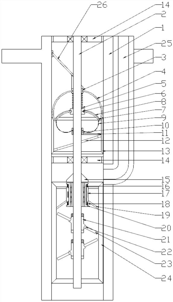
[0021] like figure 1 As shown, the present invention is an automatic air-exhausting pile perfusion device, which includes a perfusion device housing, an air suction valve, and a mud discharge valve. The mud discharge valve and the suction valve are arranged in the perfusion device housing; wherein the perfusion device housing A rotating drive shaft is connected through two sets of hollowed-out rotating support discs; the mud discharge valve includes a mud guiding cylinder; the suction valve includes a pushing mechanism; the pushing mechanism includes a suction cylinder fixed on the inner wall of the injector shell The rotating support plate is located at the ...


PUM


Abstract

The invention relates to a pile filling machine capable of automatically exhausting air. The machine comprises a filling machine outer shell, an air sucking valve and a mud discharge valve; the mud discharge valve and the air sucking valve are arranged in the filling machine outer shell; a rotary driving shaft is rotationally connected into the filling machine outer shell through two sets of hollowed-out rotary support discs; the mud discharge valve comprises a mud guide cylinder; the mud guide cylinder is connected to a support sleeve; the mud discharge valve further comprises multiple mud discharge pieces; mud discharge openings are formed in the mud discharge pieces; the mud discharge pieces are aslant arranged relative to the axis of the rotary driving shaft; the air sucking valve comprises an air sucking cylinder; an air sucking airbag is arranged in the air sucking cylinder; and the end part of a concrete injecting pipe is opened on the inner wall of the filling machine outer shell between the mud guide cylinder and the air sucking cylinder. The mud discharge valve can stir concrete through rotation of the rotary driving shaft; the concrete can be extruded for exhausting through the mud discharge pieces arranged in a mirror symmetry manner; and meanwhile, through arrangement of an arc opening, the concrete can be discharged to the next layer after extrusion, so that the exhausting and the high-density extrusion are synchronously realized.

Description

technical field [0001] The invention relates to a pile injector for automatically exhausting air, which belongs to the field of cast-in-place piles. Background technique [0002] Cast-in-situ piles are a technique for forming piles on soft soil surfaces that are not suitable for piling. The main technical difficulty is whether air holes will be generated during the process of pouring piles, because the generation of air holes will seriously affect the strength of piles. At the same time, the concrete in the piles Density is also very important; therefore, during the pile pouring process, the inside of the pile is generally stirred by a mixer step by step to discharge mud, while ensuring the density of the concrete, but the steps of step-by-step pouring and stirring are prone to partial solidification of the concrete As a result, the concrete poured in the later period cannot be fully mixed with the concrete poured in before, resulting in concrete stratification affecting the...

Claims


Application Information

Patent Timeline
Patent Type & Authority Patents(China)
IPC IPC(8): E02D15/02E02D5/34
CPCE02D5/34E02D15/02
Inventor 汪长仁
Owner 山东鲁中基础工程有限公司
Features
  • R&D
  • Intellectual Property
  • Life Sciences
  • Materials
  • Tech Scout
  • Unparalleled Data Quality
  • Higher Quality Content
  • 60% Fewer Hallucinations
Learn More