Hydraulic-driving coring tool for complex well

A hydraulic and complex technology, applied in the direction of extraction of undisturbed cores, earth-moving drilling, etc., can solve the problems of affecting the progress of coring, inability to cut pins, and long coring time, so as to improve the efficiency and quality of coring, and improve the efficiency of coring. Efficient and easy to operate

Active Publication Date: 2018-12-07
YANGTZE UNIVERSITY
View PDF7 Cites 9 Cited by
  • Summary
  • Abstract
  • Description
  • Claims
  • Application Information

AI Technical Summary

Problems solved by technology

[0003] The object of the present invention is to address the above-mentioned deficiencies in the prior art, to provide a hydraulically driven drilling tool that is suitable for coring operations in high-pressure wells, high-inclination wells, and complex wells with interlaced soft and hard formations, and can circulate self-cleaning drilling tools with large displacement. The inner cylinder and the bottom of the well can effectively avoid the occurrence of core jamming accidents, the steel ball does not need to stop drilling, the core cutting is neat, and the efficiency of coring is greatly improved. The hydraulically driven coring tool; solves the problem that the existing technology encounters high-inclination wells, complex wells with soft and hard formations, and cannot cut the pins, so that the stuck-type core claws cannot shrink and cut the core; and cannot self-clean the inner cylinder and the bottom of the well. It is easy to cause core plugging, and the drill needs to be stopped when pitching, resulting in long coring time, affecting the progress of coring, low work efficiency, and unable to meet the requirements of high-quality, large-size, and large-quantity cores.

Method used


Image

  • Hydraulic-driving coring tool for complex well
  • Hydraulic-driving coring tool for complex well
  • Hydraulic-driving coring tool for complex well

Examples


Embodiment Construction

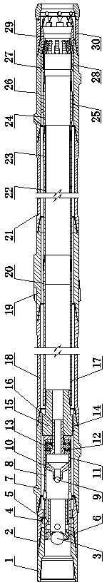
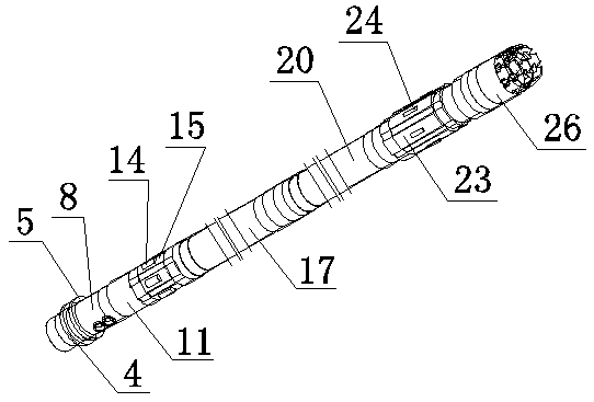
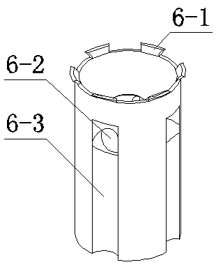
[0026] The implementation of the hydraulically driven coring tool for complex wells will be described in further detail below in conjunction with the accompanying drawings (see Figure 1-7 ):

[0027]A hydraulically driven coring tool for complex wells, which consists of a bearing shaft 8, a back pressure ball 9, a back pressure ball seat 10, a bearing seat 11, a two-way thrust ball bearing 12, a shear pin 23, a shrink The neck sleeve 27, the outer core barrel assembly, the inner core barrel assembly, the suspension assembly, the inner barrel centering mechanism, the core claw assembly and the coring bit 30 are composed; the outer core barrel assembly consists of an upper joint 1 and a safety joint in turn 2. The upper spiral centralizer 7, the first outer core barrel 18, the middle spiral centralizer 19, the second outer core barrel 21 and the lower spiral centralizer 26 are connected with male and female threads; the inner core barrel assembly It is composed of the upper sh...


PUM


Abstract

The invention relates to a hydraulic-driving coring tool for a complex well, and belongs to the technical field of oil drilling exploitation down-hole tools. The hydraulic-driving coring tool is formed by an inner rock core cylinder assembly, an outer rock core cylinder assembly and the like; the outer rock core cylinder assembly is composed of an upper connector, a safety connector, an upper spiral centralizer, a middle spiral centralizer, a lower spiral centralizer, a first-section outer rock core cylinder and a second-section rock core cylinder; the inner rock core cylinder assembly is composed of an inner-cylinder upper shaft, a first-section inner rock core cylinder, a second-section inner rock core cylinder and a dual-layer aluminum alloy liner; a bearing hanging steel ball is hung on an inner shoulder of the safety connector through a ball hanging runway, a clamping sleeve ball base is installed on a hanging assembly, centering of the inner cylinder is guaranteed through an inner-cylinder centralizing mechanism, and the hydraulic-driving coring tool is suitable for large-inclined-well coring; a rock-core-claw assembly is composed of a necking sleeve, a clamp-type rock core claw and a clamping-plate rock core claw, in a soft formation, the hanging steel ball and a ball hole of the clamping sleeve ball base are aligned and slide into the clamping sleeve ball base, the hanging assembly is unlocked, and a rock core is cut off through the clamping-plate rock core claw; in a hard formation, pressure of the inner cylinder is increased and subjected to pump suffocation, a drilling tool is lifted when the pressure reaches 16 MPa, and the rock core is clamped and pulled off through the clamp-type rock core claw. The hydraulic-driving coring tool is suitable for core cutting operation under different geological conditions.

Description

technical field [0001] The invention relates to a hydraulically driven coring tool for complex wells, belonging to the technical field of downhole tools for oil drilling. Background technique [0002] Nowadays, oil and gas exploration and development operations have gradually shifted from shallow wells, low-pressure wells, and small-inclination wells to high-pressure wells, high-inclination wells, and complex wells with interlaced soft and hard geological conditions. The effect of coring in complex formations such as hard interlacing is not satisfactory, and it can no longer meet the requirements of obtaining high-quality, large-size, and large-scale cores. The commonly used self-locking and pressurized coring tools not only have a small scope of application, but also are not sophisticated enough in small areas; currently, the mechanical pressurized coring tools widely used in major oil fields have the following defects. One is When the well deviation is large, the four ste...

Claims


Application Information

Patent Timeline
Patent Type & Authority Applications(China)
IPC IPC(8): E21B25/00E21B25/10
CPCE21B25/00E21B25/10
Inventor 刘少胡鲁孟良
Owner YANGTZE UNIVERSITY
Why Eureka
Try Eureka