Stirring paddle for mechanical stirring apparatus

A mechanical stirring and stirring paddle technology, applied in mixer accessories, mixers, dissolving and other directions, can solve the problems of high cost, hub fracture accident, long production cycle, etc., and achieve the effect of low cost, short production cycle and reliable performance

Inactive Publication Date: 2013-02-13
NO 9 METALLURGICAL CONSTR
View PDF0 Cites 1 Cited by
  • Summary
  • Abstract
  • Description
  • Claims
  • Application Information

AI Technical Summary

Problems solved by technology

[0004] In view of the above situation, the purpose of the present invention is to provide a new type of stirring paddle for mechanical stirring equipment, which c

Method used


Image

  • Stirring paddle for mechanical stirring apparatus
  • Stirring paddle for mechanical stirring apparatus
  • Stirring paddle for mechanical stirring apparatus

Examples


Embodiment Construction

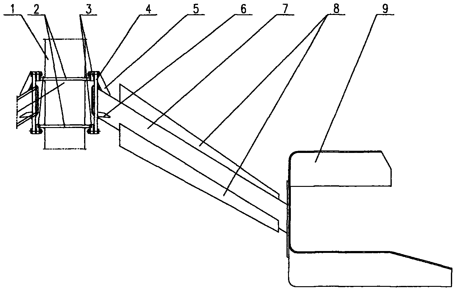
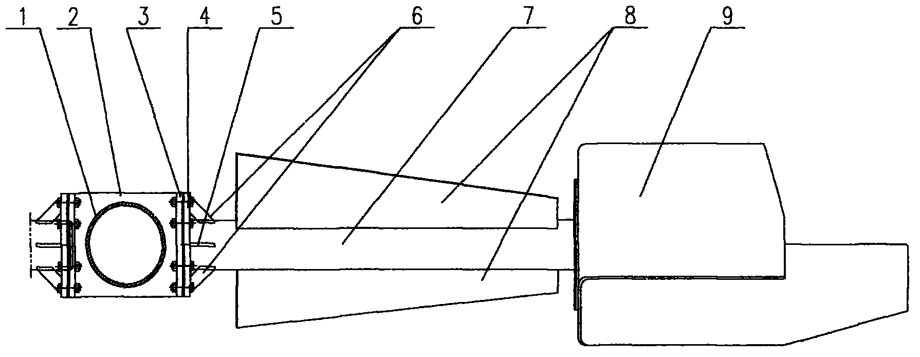
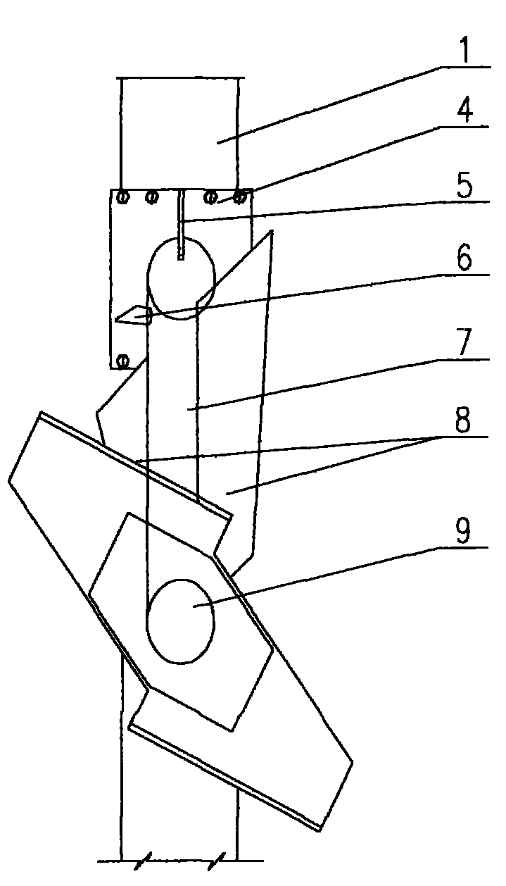
[0023] The specific implementation of the present invention will be described in detail below in conjunction with the accompanying drawings.

[0024] Depend on Figure 1-4 Shown, the present invention comprises stirring paddle support seat and stirring paddle, and stirring paddle is made of fulcrum flange 4, stiffener plate 5, stiffener plate 6, inner paddle pivot 7, inner paddle blade 8 and outer paddle blade 9, the fulcrum flange 4 is mounted on the inner paddle fulcrum 7, there is a first rib plate 5 and a second rib plate 6 between the fulcrum flange 4 and the inner paddle fulcrum 7, and the inner paddle fulcrum 7 is The inner paddle blade 8 is symmetrically installed on the side, the outer paddle blade 9 is installed on the outer end of the inner paddle shaft 7, the stirring paddle support seat is installed on the stirring main shaft 1, and the stirring paddle support seat is composed of a support plate 2 and a fixed frame 3. The support plate 2 and the fixed frame 3 are...


PUM


Abstract

The present invention relates to a stirring paddle for a mechanical stirring apparatus. The stirring paddle comprises a stirring paddle support base and stirring paddle blades, wherein the stirring paddle support base comprises a stirring main shaft, a support plate fixedly arranged on the stirring main shaft and a fixation frame connected with the support plate. The stirring paddle has characteristics of simple and unique structure, low cost and short production cycle, provides creative improvement for the stirring paddle for the existing domestic mechanical stirring equipment, is suitable for hydrometallurgy, chemical industry, phosphate fertilizer, and other industries, and provides significant economic benefits and social benefits. In addition, based on a large amount of designs, manufactures and installations of stirring equipment and various steel components, the stirring paddle is completed through careful design calculation and assurance of the strength required by stirring.

Description

technical field [0001] The invention relates to a stirring device, in particular to a stirring paddle for mechanical stirring equipment. Background technique [0002] At present, most domestic alumina factories use alumina seed decomposition tanks with diameters of φ14m, φ12m, φ10.5m, and φ7m. The height of the tank ranges from 18m to 36.5m, and the maximum volume reaches 5400m3. The φ14×36.5m seed separation tank is the largest in China. Solid-liquid suspension stirring tank. In 1990, the intermig paddle introduced in Guangxi was used in φ14m sub-troughs, and the stirring effect was not ideal. Therefore, my country's design institute improved the intermig paddle, and the effect was good, and it began to be widely used in China. In recent years, my country's alumina industry has developed rapidly, and nearly a thousand φ14m sub-troughs have been newly built or rebuilt. [0003] Since the diameter of the four-layer blades on the upper part of the 14m kind of tank currently...

Claims


Application Information

Patent Timeline
IPC IPC(8): B01F15/00
Inventor 王尤祥张廷松杨飞燕孟庆霞
Owner NO 9 METALLURGICAL CONSTR
Why Eureka
Try Eureka