Tunnel lining structure using concrete filled steel tubes and laminated plates and construction method thereof

A technology of concrete filled steel tubes and steel tubes, applied in tunnel linings, tunnels, shaft linings, etc., can solve the problems that the steel arch and shotcrete are difficult to work together at the same time, other tunnel processes and transportation interference, and the poor adaptability of special-shaped sections, etc. Achieve significant economic value and comprehensive benefits, shorten the construction period, and reduce the amount of steel used

Active Publication Date: 2018-12-07
KUNMING UNIV OF SCI & TECH
View PDF7 Cites 26 Cited by
  • Summary
  • Abstract
  • Description
  • Claims
  • Application Information

AI Technical Summary

Problems solved by technology

[0002] The initial support of the traditional tunnel lining structure mainly adopts grid steel frame or I-shaped steel frame as the skeleton structure. The grid steel frame or I-shaped steel frame has good toughness, but the compressive strength is not high. A large amount of steel can meet the needs of the initial support strength. At the same time, it is difficult for the steel arch frame and the shotcrete to bear the external load at the same time; while the secondary lining construction of the tunnel mainly adopts the cast-in-place construction of the formwork trolley, and the formwork platform The car body is huge and heavy, and it needs to occupy a lot of tunnel space during the construction period, which seriously interferes with other processes and transportation in the tunnel; at the same time, it also has the disadvantages of long construction period and poor adaptability to special-shaped sections.

Method used


Image

  • Tunnel lining structure using concrete filled steel tubes and laminated plates and construction method thereof
  • Tunnel lining structure using concrete filled steel tubes and laminated plates and construction method thereof
  • Tunnel lining structure using concrete filled steel tubes and laminated plates and construction method thereof

Examples


Embodiment 1

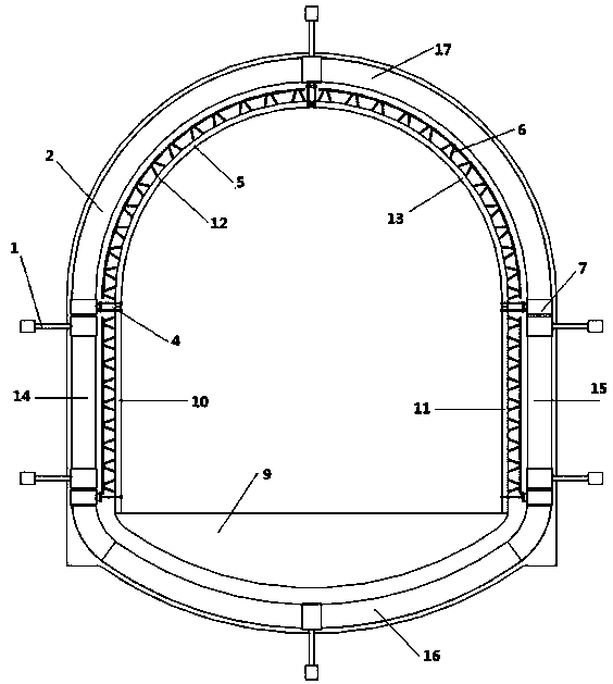
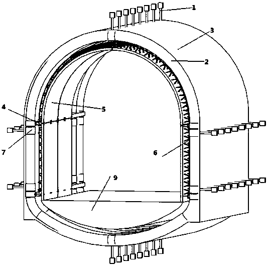
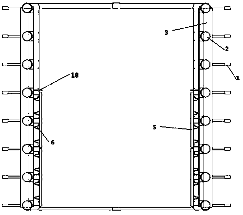
[0042] Embodiment 1: as Figure 1-5 As shown, a tunnel lining structure using concrete-filled steel tubes and laminated slabs. The composite slabs are installed with the concrete-filled steel tube arch frame as the support. The longitudinal and circumferential steel bars are bound on the truss bars of the laminated slabs, and then concrete is poured to form the secondary lining structure of the tunnel.

[0043] Further, the tunnel lining structure using steel pipe concrete and laminated slabs in the present invention specifically includes anchor connectors 1, steel pipe arches 2, steel mesh shotcrete 3, laminated slab supports 4, laminated slabs 5, and laminated slab truss bars 6;

[0044] Before the construction of the tunnel, the steel pipe arch frame 2 is prefabricated in sections outside the tunnel, the laminated plates 5 are prefabricated in pieces, and the anchor connectors 1 are reserved in the surrounding rock, and the prefabricated steel pipe arch frame 2 is transporte...

Embodiment 2

[0062] Example 2, such as Figure 1-5 As shown, a tunnel lining structure and construction method using steel pipe concrete and laminated slabs, this embodiment is the same as embodiment 1, wherein:

[0063] Further, the steel pipe arch 2 adopts a seamless round steel pipe with a diameter of 25 cm or a square steel pipe with a side length of 25 cm, the thickness of the steel pipe is 2 cm, and the steel pipe arch 2 is fixed to the initial support of the tunnel by the pre-embedded anchor connector 1 Instead of the grid steel frame or I-shaped steel frame in the primary support, the distance between each steel pipe arch frame 2 is 1.5m. The specific parameters depend on the type of tunnel surrounding rock and are determined by calculation or engineering analogy.

[0064] Further, the longitudinal width of the laminated board 5 is equivalent to the distance between the three steel pipe arches 2; the thickness of the laminated board is 8 cm; the inside of the laminated board 5 is m...

Embodiment 3

[0065] Example 3, such as Figure 1-5 As shown, a tunnel lining structure and construction method using steel pipe concrete and laminated slabs, this embodiment is the same as embodiment 1, wherein:

[0066] Further, the steel pipe arch 2 adopts a seamless round steel pipe with a diameter of 20cm or a square steel pipe with a side length of 20cm, the thickness of the steel pipe is 1.6cm, and the steel pipe arch 2 is fixed on the initial support of the tunnel by the embedded anchor connector 1. Instead of the grid steel frame or I-shaped steel frame in the primary support, the distance between each steel pipe arch frame 2 is 1.2m. The specific parameters depend on the type of tunnel surrounding rock and are determined by calculation or engineering analogy.

[0067] Further, the longitudinal width of the laminated board 5 is equivalent to the distance between the three steel pipe arches 2; the thickness of the laminated board is 6 cm; the inside of the laminated board 5 is mixed...


PUM


Abstract

The invention relates to a tunnel lining structure using concrete filled steel tubes and laminated plates and a construction method thereof, and belongs to the technical field of tunnel construction.A concrete filled steel tubular arch frame is used as a support to install the laminated plates, longitudinal and circumferential rebars are bound on truss rebars of the laminated plates, and then concrete is poured to form a secondary lining structure of a tunnel. According to the tunnel lining structure using the concrete filled steel tubes and the laminated plates and the construction method thereof, the secondary lining construction technology of the tunnel with saving space, fast construction speed and strong adaptability of special-shaped section is proposed, the construction process oftunnel secondary lining is improved, and it is helpful to quicken construction schedule and save construction cost; the stiffness and bearing capacity of the initial supporting structure are greatly improved, the adaptability of the special-shaped section of the tunnel lining construction is improved, and the section prefabricated assembling construction of steel pipes is convenient and fast.

Description

technical field [0001] The invention relates to a tunnel lining structure using steel tube concrete and laminated plates and a construction method, belonging to the technical field of tunnel construction. Background technique [0002] The initial support of the traditional tunnel lining structure mainly adopts grid steel frame or I-shaped steel frame as the skeleton structure. The grid steel frame or I-shaped steel frame has good toughness, but the compressive strength is not high, so it needs to be used in weak surrounding rock areas. A large amount of steel can meet the needs of the initial support strength. At the same time, it is difficult for the steel arch frame and the shotcrete to bear the external load at the same time; while the secondary lining construction of the tunnel mainly adopts the cast-in-place construction of the formwork trolley, and the formwork platform The vehicle is bulky and heavy, and needs to occupy a large amount of tunnel space during constructi...

Claims


Application Information

Patent Timeline
Patent Type & Authority Applications(China)
IPC IPC(8): E21D11/10E21D11/14E21D11/18E21D20/00
CPCE21D11/003E21D11/10E21D11/14E21D11/18E21D20/00
Inventor 谢洪涛
Owner KUNMING UNIV OF SCI & TECH
Why Eureka
Try Eureka