Tunnel lining structure with steel tube concrete as skeleton and slip-form construction method

A technology of steel pipe concrete and shotcrete, which is applied in the direction of tunnel lining, tunnel lining, shaft lining, etc. It can solve the problems of poor adaptability of special-shaped sections, long construction period, and large space occupation, and achieves the reduction of steel consumption, convenient and quick construction, and economical construction. template effect

Active Publication Date: 2018-11-30
KUNMING UNIV OF SCI & TECH
View PDF4 Cites 13 Cited by
  • Summary
  • Abstract
  • Description
  • Claims
  • Application Information

AI Technical Summary

Problems solved by technology

[0003] The technical problem to be solved by the present invention is: the present invention provides a tunnel lining structure and a sliding form construction method with steel pipe concrete as the skeleton, which are used to overcome the large space occupation, long construction period, and Shortcomings such as poor adaptability of special-shaped sections; the present invention proposes a space-saving, fast-construction tunnel secondary lining construction technology with strong adaptability to special-shaped sections by adopting the slip-form construction technology, which improves the construction technology of the secondary lining of tunnels and helps To speed up the construction progress and save construction costs

Method used


Image

  • Tunnel lining structure with steel tube concrete as skeleton and slip-form construction method
  • Tunnel lining structure with steel tube concrete as skeleton and slip-form construction method
  • Tunnel lining structure with steel tube concrete as skeleton and slip-form construction method

Examples


Embodiment 1

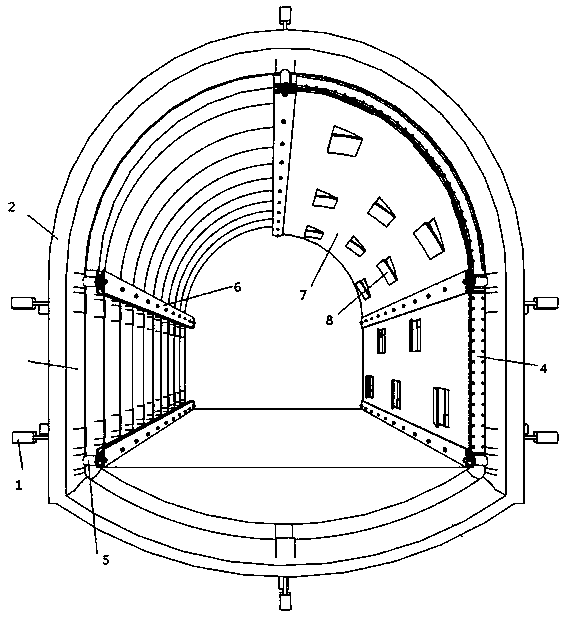
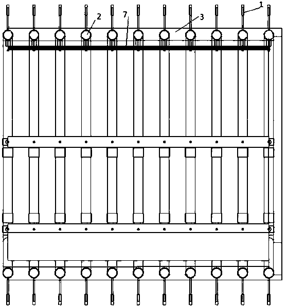
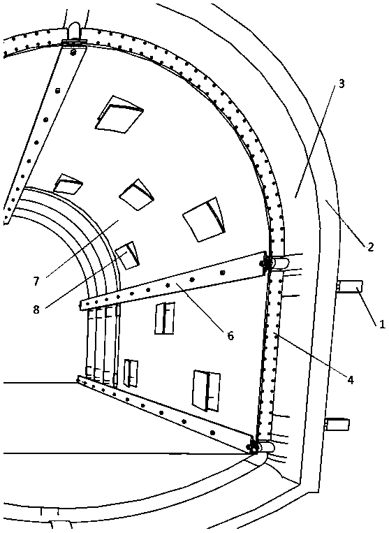
[0038] Embodiment 1: as Figure 1-4 As shown, a tunnel lining structure with steel pipe concrete as the skeleton includes anchor connector 1, steel pipe arch frame 2, steel mesh shotcrete 3, steel bar support 4, formwork track support device 5, formwork track 6, sliding formwork 7 and Openable window 8; before the tunnel construction, prefabricate the steel pipe arch frame 2 in sections outside the tunnel, reserve anchor connectors 1 in the surrounding rock, transport the segmentally prefabricated steel pipe arch frame 2 to the working face for assembly, and install the steel pipe arch frame Frame 2 is fixed close to the surrounding rock surface through anchor connector 1, high-strength concrete is poured into steel pipes through reserved pouring holes to form steel pipe concrete arches, steel mesh shotcrete 3 is constructed between and outside steel pipe concrete arches, The concrete-filled steel tube arch frame is fixed together with the steel mesh shotcrete; the formwork tr...

Embodiment 2

[0064] Embodiment 2: as Figure 1-4 As shown, a tunnel lining structure and a sliding form construction method with steel pipe concrete as the skeleton, this embodiment is the same as Embodiment 1, wherein:

[0065] Further, the steel pipe arch 2 adopts a seamless round steel pipe with a diameter of 25 cm or a square steel pipe with a side length of 25 cm, and the thickness of the steel pipe is 2 cm. Instead of the grid steel frame or I-shaped steel frame in the primary support, the distance between each steel pipe arch frame 2 is 1.5m. The specific parameters depend on the type of tunnel surrounding rock and are determined by calculation or engineering analogy.

[0066] Further, in the step Step1, the steel pipe arch 2 can be a seamless round steel pipe with a diameter of 25 cm, or a square steel pipe with a variable length of 25 cm, the wall thickness of the steel pipe is 2 cm, and the steel arch is prefabricated in four sections; The size is determined according to the inn...

Embodiment 3

[0067] Embodiment 3: as Figure 1-4 As shown, a tunnel lining structure and a sliding form construction method with steel pipe concrete as the skeleton, this embodiment is the same as Embodiment 1, wherein:

[0068] Further, the steel pipe arch 2 adopts a seamless round steel pipe with a diameter of 22cm or a square steel pipe with a side length of 22cm, and the thickness of the steel pipe is 1.7cm. In the support, instead of the grid steel frame or I-shaped steel frame in the initial support, the distance between the steel pipe arches 2 is 1.3m. The specific parameters depend on the type of tunnel surrounding rock and are determined by calculation or engineering analogy.

[0069] Further, in the step Step1, the steel pipe arch 2 can be a seamless round steel pipe with a diameter of 22cm, or a square steel pipe with a variable length of 22cm, the wall thickness of the steel pipe is 1.7cm, and the steel arch is prefabricated in four sections; the steel pipe arch The size of th...


PUM

PropertyMeasurementUnit
diameteraaaaaaaaaa
lengthaaaaaaaaaa
thicknessaaaaaaaaaa

Abstract

The invention relates to a tunnel lining structure with steel tube concrete as the skeleton and a slip-form construction method, and belongs to the field of tunnel construction. The method includes the steps that steel tube arch frames are prefabricated segment by segment and then are assembled, the steel tube arch frames are closely attached to the surface of surrounding rock to be fixed, high-strength concrete is poured into steel tubes to form steel tube-concrete arch frames, concrete is sprayed between the steel tube-concrete arch frames and to external construction reinforcement meshes, and the steel tube-concrete arch frames are fixed together with the reinforcement mesh sprayed concrete through anchoring connectors; form track support devices are installed on the surfaces of the steel tube-concrete arch frames, form tracks are installed on the form track support devices, and then reinforcement supports and slip forms are installed. The method can adapt to various tunnel internalcontour dimensions and effectively overcome the defect that a form trolley cannot adapt to variable-cross-section tunnel construction; besides, the occupation of tunnel construction space is very small, and other processes are not affected; the slip-form construction is easy and fast, the forms are saved, and thus the method has significant economic benefits and promotional value.

Description

technical field [0001] The invention relates to a tunnel lining structure with steel pipe concrete as a skeleton and a sliding form construction method, belonging to the technical field of tunnel construction. Background technique [0002] The initial support of the traditional tunnel lining structure mainly adopts grid steel frame or I-shaped steel frame as the skeleton structure. The grid steel frame or I-shaped steel frame has good toughness, but the compressive strength is not high, so it needs to be used in weak surrounding rock areas. A large amount of steel can meet the needs of initial support strength; while the secondary lining construction mainly adopts formwork trolley cast-in-place construction, the formwork trolley is huge and heavy, and special rails need to be installed for propulsion construction. During the construction period, it needs to occupy a large amount of tunnel space, which seriously interferes with other processes and transportation in the tunnel...

Claims


Application Information

Patent Timeline
Patent Type & Authority Applications(China)
IPC IPC(8): E21D11/10E21D11/14E21D11/18E21D20/00
CPCE21D11/003E21D11/10E21D11/14E21D11/18E21D20/00
Inventor 谢洪涛
Owner KUNMING UNIV OF SCI & TECH
Why Eureka
Try Eureka