A non-metallic vertical lift test device

A test device and vertical lifting technology, which is applied in the direction of machine/support, supporting machine, electromagnetic field characteristics, etc., can solve problems such as non-compliance, achieve automatic adjustment of lifting height, improve use safety, and improve efficiency.

Active Publication Date: 2020-11-17
CHINA SHIP DEV & DESIGN CENT
View PDF8 Cites 0 Cited by
  • Summary
  • Abstract
  • Description
  • Claims
  • Application Information

AI Technical Summary

Problems solved by technology

There is no similar non-metallic test rod in China, and the metal lifting height is mostly 1m~4m according to the civil standard test requirements, which does not meet the requirements of this project

Method used


Image

  • A non-metallic vertical lift test device
  • A non-metallic vertical lift test device
  • A non-metallic vertical lift test device

Examples


Embodiment Construction

[0029] The present invention will be further described below in conjunction with accompanying drawing.

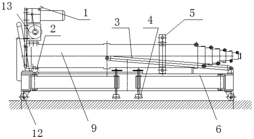
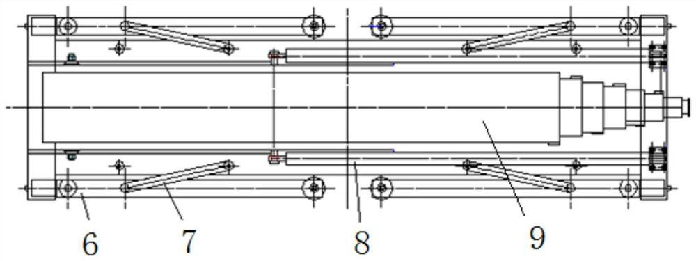
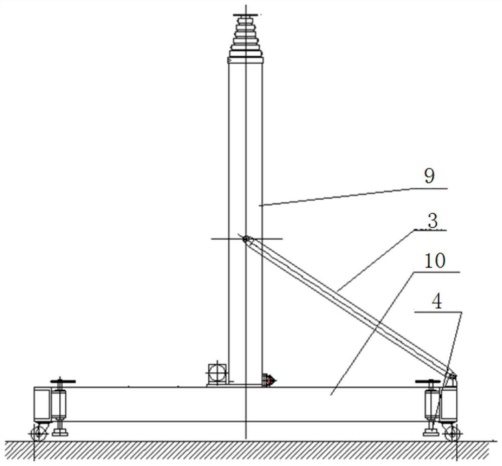
[0030] like Figure 1-6 As shown, the present embodiment provides a non-metallic vertical lifting test device, including a movable base 10, on which a telescopic test rod 9 is arranged, and the test rod 9 is movably arranged on the base 10 , a support rod 3 is hinged on the test rod 9, the other end of the support rod 3 is hinged with the base 10, and is used to support the test rod 9 when the test rod is upright, and the test rod 9 realizes its expansion and contraction through the lifting drive mechanism , the two sides of base 10 are symmetrically provided with retractable legs 6 and fixing devices for fixing the base.

[0031] In this embodiment, the movable base 10 is made of reinforced epoxy fiberglass, and four universal wheels are installed at the four corners of the bottom surface to form the movable base 10 . 4 retractable legs are housed on both sides of the ba...


PUM


Abstract

The invention discloses a nonmetallic vertical lifting testing device. The nonmetallic vertical lifting testing device is characterized in that the nonmetallic vertical lifting testing device comprises a movable base, a telescopic testing rod is arranged on the base, the testing rod is movably arranged on the base, folding and unfolding of the testing rod are achieved through a testing rod foldingand unfolding mechanism, the testing rod achieves telescoping through a lifting driving mechanism, and foldable supporting legs and fixing devices used for fixing the base are symmetrically arrangedon the two sides of the base. According to the nonmetallic vertical lifting testing device, the functions of testing meter fixing, automatic lifting height adjusting and flexible moving can be effectively achieved, and bad influences can not be generated to radio frequency microwave testing.

Description

technical field [0001] The invention relates to the field of radio frequency and microwave testing, in particular to a non-metallic vertical lift testing device. Background technique [0002] When testing radio frequency and microwave electromagnetic environment characteristics, we often encounter the following common test scenarios: 1. Keep the electromagnetic wave transmitting antenna level with the radio frequency and microwave antenna to be tested, so that the electromagnetic wave is incident vertically and evenly as possible to obtain the measured 2. Raise the transmitting antenna to a certain height to reduce the reflection of electromagnetic waves on the ground, so as to accurately collect the radiation electromagnetic environment of the transmitting antenna; 3. Fix the field strength measuring probe at a certain height of the space One point, to obtain the spatial characteristics of the electromagnetic wave field strength. For the above scenarios, it is necessary to...

Claims


Application Information

Patent Timeline
Patent Type & Authority Patents(China)
IPC IPC(8): G01R29/08F16M11/10F16M11/04
CPCF16M11/046F16M11/10
Inventor 张瑞吴楠
Owner CHINA SHIP DEV & DESIGN CENT
Why Eureka
Try Eureka