Combustion device

A combustion device and fuel technology, which is applied to burners, combustion methods, combustion types, etc., can solve the problems of single applicable fuel and insufficient combustion, and achieve the effect of improving cost efficiency and combustion efficiency.

Active Publication Date: 2018-12-07
付笔贤
View PDF9 Cites 4 Cited by
  • Summary
  • Abstract
  • Description
  • Claims
  • Application Information

AI Technical Summary

Problems solved by technology

[0004] In order to overcome the defects of insufficient combustion and single applicable fuel in the prior art combustion device, an embodiment of the present invention provides a combustion device, which includes a first housing, and further includes:

Method used


Image

  • Combustion device
  • Combustion device
  • Combustion device

Examples


no. 1 example

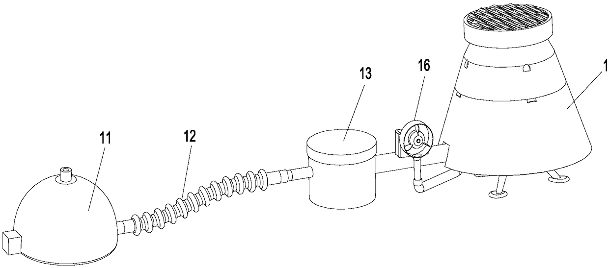
[0054] Please refer to Figure 1 to Figure 8 As shown, the embodiment of the present invention discloses a combustion device, which may specifically be an integrated oil stove or alcohol stove, including a first shell 1, and also includes:

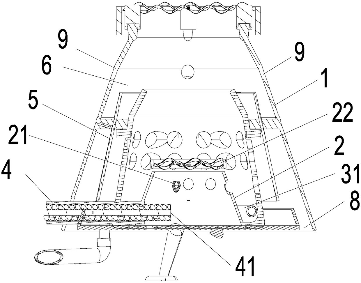
[0055] The gasification chamber 2 is arranged in the first casing 1 and includes an air inlet 21 and an airflow injection outlet 22;

[0056] A blower system, comprising a fan 16 and an air duct connected to the fan 16, the air duct extends to the gasification chamber 2 and communicates with the air inlet 21;

[0057] The fuel supply system includes an ignition end 41 protruding into the gasification chamber, and the heat generated by the ignition end 41 during combustion will gasify the fuel into combustible gas.

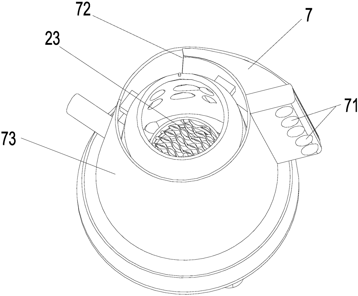
[0058] As an improvement to this embodiment, the above-mentioned gasification chamber 2 includes a first heat feedback surface, on which a plurality of airflow injection outlets 22 are formed. The thermal feedback surface in ...

no. 2 example

[0085] Please refer to Figure 9 As shown, it is a perspective view of the first casing of the second embodiment of the present invention. The difference from the first embodiment is that the combustion device also includes a spiral air inlet nozzle 17 arranged at the second heat feedback surface, The spiral air inlet nozzle 17 includes an annular casing 171, which is connected to the airflow injection outlet at the bottom, and the spiral air inlet nozzle 17 also includes an air inlet opened on the outside of the annular casing 171 172, and an air outlet (not shown in the figure) opened inside the annular housing 171 and communicated with the air inlet 172.

[0086] In the embodiment of the present invention, by further shrinking the area of ​​the flame injection port, the flame injection speed and flame temperature are increased, and the combustion device can be used as a blowtorch. At the same time, since the flame injection port adopts a side annular air intake, the externa...

no. 3 example

[0088] Please refer to Figure 10 to Figure 18 As shown, the embodiment of the present invention discloses a combustion device, which may specifically be an integrated oil stove or alcohol stove, including a first shell, and also includes:

[0089] The gasification chamber 2' is located in the first housing, including an air inlet 21' and an air jet outlet 22';

[0090] Blowing system, comprising blower fan 16' and the air duct connected with said blower fan 16', said air duct extends to said gasification chamber 2' and communicates with said air inlet 21';

[0091] The fuel supply system includes an ignition end 41' protruding into the gasification chamber, and the heat generated by the ignition end 41' during combustion will gasify the fuel into combustible gas.

[0092] As an improvement to this embodiment, the gasification chamber 2' can adopt a trumpet-shaped structure with a large bottom and a small top to facilitate the formation of the above-mentioned high-temperature...


PUM


Abstract

The invention relates to thermal equipment, in particular to a combustion device. The combustion device comprises a first shell body and further comprises a gasification chamber, an gas blowing system, and a fuel supply system, wherein the gasification chamber is arranged in the first shell body and comprises a gas inlet and a gas flow jetting outlet, the gas blowing system comprises a fan and a gas channel connected with the fan, the gas channel extends to the gasification chamber and communicates with the gas inlet, the fuel supply system comprises an ignition end extending into the gasification chamber, and the heat generated in the combustion process of the ignition end is used for gasifying fuel into combustible gas. According to the combustion device, the fuel is effectively utilized, and the combustion efficiency of the combustion device is improved.

Description

technical field [0001] The invention relates to thermal equipment, in particular to a combustion device. Background technique [0002] Existing combustion devices usually use liquid or solid as the main fuel, and the fuel is directly burned to form a flame by igniting and heating the fuel. Due to structural reasons, some of these combustion devices have low combustion efficiency, resulting in insufficient fuel combustion, resulting in Waste of resources and pollute the environment; there are also some, because of the use of more expensive fuels, such as butane gas, the cost-effectiveness ratio is too low and it is uneconomical to use. [0003] In order to overcome the above shortcoming of existing combustion device, especially carry out this invention research. Contents of the invention [0004] In order to overcome the defects of insufficient combustion and single applicable fuel in the prior art combustion device, an embodiment of the present invention provides a combus...

Claims


Application Information

Patent Timeline
Patent Type & Authority Applications(China)
IPC IPC(8): F23D11/22F23D11/44F23D11/36
CPCF23D11/22F23D11/36F23D11/446F23D14/02F23D14/46F23D14/62
Inventor 付笔贤
Owner 付笔贤
Why Eureka
Try Eureka