Storage battery pole plate circulation drying device

A cycle drying and storage battery technology, which is applied in the direction of lead-acid battery electrodes, dry solid materials, dry goods processing, etc., can solve the problems that the conveying device occupies a large area and cannot cycle dry the plates, and achieves good drying effect and simple structure , The effect of speeding up the production speed

Inactive Publication Date: 2018-12-07
安徽迅启电源科技有限公司
View PDF11 Cites 1 Cited by
  • Summary
  • Abstract
  • Description
  • Claims
  • Application Information

AI Technical Summary

Problems solved by technology

[0004] The battery plates of the above-mentioned patent pass through the pre-drying device and the drying box sequentially in the conveying device. To increase the production capacity, the conveying device must be lengthened, which leads to a large area of ​​the conveying device and cannot cycle dry the plates. Therefore, the present invention provides a battery plate circulation drying device

Method used


Image

  • Storage battery pole plate circulation drying device
  • Storage battery pole plate circulation drying device
  • Storage battery pole plate circulation drying device

Examples


Embodiment 1

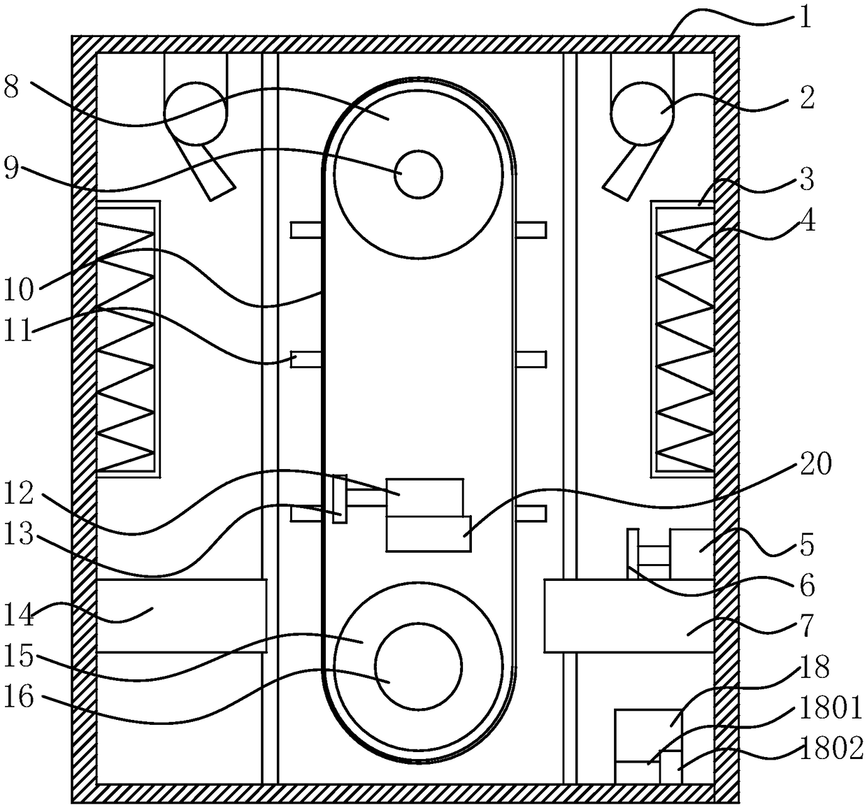
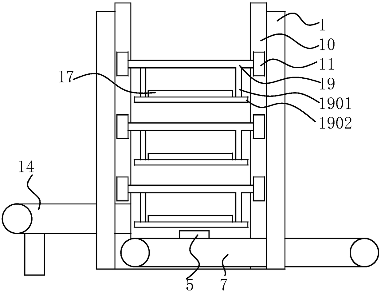
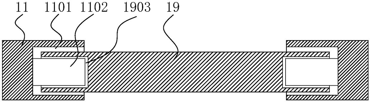
[0020] Such as figure 1 , figure 2 As shown, the present invention provides a battery plate circulation drying device, including a housing 1, a conveying device arranged in the housing 1, and a control device. The conveying device includes a driving wheel 15 and a driven wheel 8 oppositely arranged. The rotating shaft 9 is arranged on the upper part of the inner wall of the housing 1, and the driving wheel 15 is arranged on the lower part of the inner wall of the housing 1 and is in transmission connection with the motor 16 arranged on the inner wall of the housing 1. The driving wheel 15 is in transmission connection with the driven wheel 8 through the chain 10, and the chain 10 The connecting plate 11 is oppositely arranged on the top, and the swing rod 19 is movable between the connecting plates 11. The swing rod 19 is connected to the placement plate 1902 through the fixed rod 1901. The pole plate 17 is placed on the placement plate 1902. The two sides of the inner wall o...

Embodiment 2

[0025] Such as figure 1 , figure 2 As shown, the present invention provides a battery plate circulation drying device, including a housing 1, a conveying device arranged in the housing 1, and a control device. The conveying device includes a driving wheel 15 and a driven wheel 8 oppositely arranged. The rotating shaft 9 is arranged on the upper part of the inner wall of the housing 1, and the driving wheel 15 is arranged on the lower part of the inner wall of the housing 1 and is in transmission connection with the motor 16 arranged on the inner wall of the housing 1. The driving wheel 15 is in transmission connection with the driven wheel 8 through the chain 10, and the chain 10 The connecting plate 11 is oppositely arranged on the top, and the swing rod 19 is movable between the connecting plates 11. The swing rod 19 is connected to the placement plate 1902 through the fixed rod 1901. The pole plate 17 is placed on the placement plate 1902. The two sides of the inner wall o...


PUM


Abstract

The invention discloses a storage battery pole plate circulation drying device. The storage battery pole plate circulation drying device comprises a shell, a conveying device and a control device, wherein the conveying device and the control device are arranged in the shell; the conveying device comprises a driving wheel and a driven wheel opposite to the driving wheel; the driven wheel is arranged on the upper portion of the inner wall of the shell through a rotary shaft; the driving wheel is arranged on the lower portion of the inner wall of the shell and is in transmission connection with amotor arranged on the inner wall of the shell; the driving wheel is in transmission connection with the driven wheel through a chain; the chain is oppositely provided with connection plates, and swing rods are movably arranged between the connection plates; the swing rods are connected with storage plates through fixing rods, and pole plates are placed on the storage plates; the two sides of theinner wall of the shell are provided with electric heating wires, and protective nets are arranged outside the electric heating wires; and the top of the shell is obliquely provided fans. According tothe storage battery pole plate circulation drying device, circulation drying of the storage battery pole plates is achieved, and the storage battery pole plates can be dried for a long time.

Description

Technical field: [0001] The invention relates to the field of drying equipment, in particular to a battery plate circulation drying device. Background technique: [0002] In the production of lead-acid battery plates, it is necessary to dry the surface of the battery plates. The earliest drying method is natural air drying. This drying method has the disadvantages of low production efficiency, large space occupation and long drying time. [0003] In the patent with the publication number CN201420208410.0, the patent discloses a battery plate circulation drying device, including a frame, and a plate conveying device is installed on the frame. A pre-drying device and a drying box are installed in sequence in the conveying direction, and a humidity detection device is installed on the frame below the pre-drying device, and a humidity controller is connected to the humidity detection device, and the humidity controller is connected to the The pre-drying device is connected; t...

Claims


Application Information

Patent Timeline
Patent Type & Authority Applications(China)
IPC IPC(8): F26B15/22F26B25/00H01M4/16
CPCF26B15/22F26B25/003H01M4/16Y02E60/10
Inventor 储昭虎王根禄储宁平邓汉卿
Owner 安徽迅启电源科技有限公司
Why Eureka
Try Eureka