Chemical raw material circulating drying device

A technology of drying device and chemical raw materials, applied in drying, drying machine, drying gas arrangement and other directions, can solve problems such as insufficient drying uniformity, and achieve the effect of sufficient drying and uniform drying

Inactive Publication Date: 2021-05-04
王丽丽
View PDF12 Cites 0 Cited by
  • Summary
  • Abstract
  • Description
  • Claims
  • Application Information

AI Technical Summary

Problems solved by technology

[0003] Chemical raw materials need to be dried during the processing process, but the existing drying equipment usually simply lays the raw materials flat, and then uses a fixed air nozzle to dry them, and the positions where the hot air flows are too concentrated. As a result, the drying is not uniform enough, so a chemical raw material circulation drying device is now provided to solve this technical problem

Method used


Image

  • Chemical raw material circulating drying device
  • Chemical raw material circulating drying device
  • Chemical raw material circulating drying device

Examples


Embodiment 1

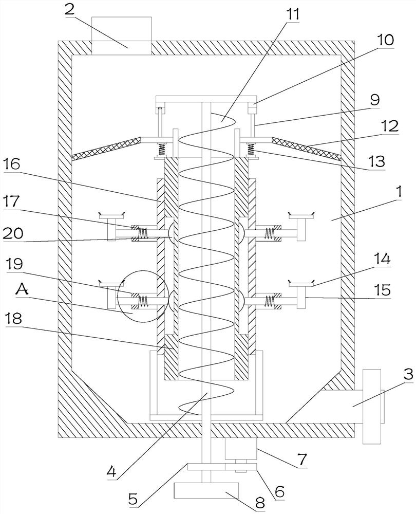
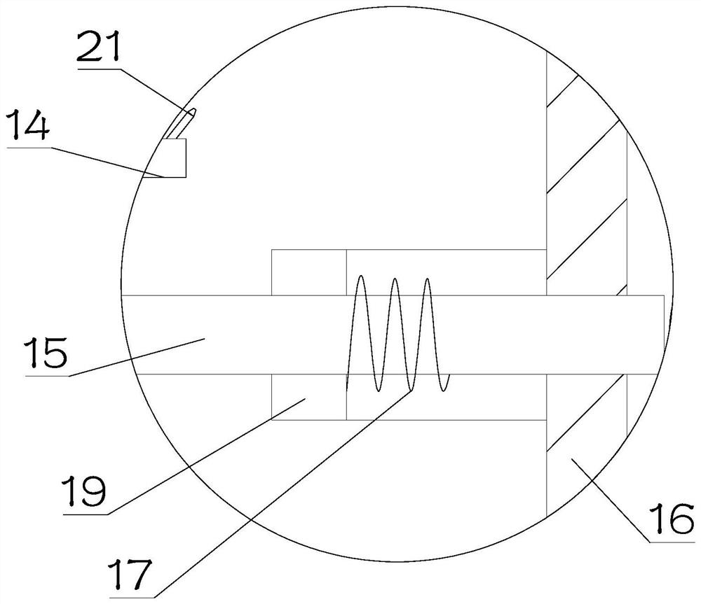
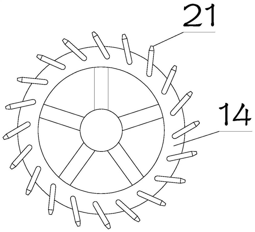
[0023] see Figure 1~3 , in Embodiment 1 of the present invention, it is a structural diagram of a chemical raw material circulation drying device provided in the embodiment of the present invention, including: a device main body 1 provided in a hollow interior, and a feeding cylinder is provided in the middle of the device main body 1 18. A self-rotating sleeve 16 is sleeved on the outside of the feeding tube 18, and a plurality of support sleeves 19 are arranged in an array outside the sleeve 16, and a reciprocating sliding connector 15 is provided inside the support sleeve 19 , the connecting piece 15 is provided with an air jet disc 14 for self-rotation; the inner through hole of the said feeding cylinder 18 is provided with a rotating shaft 4 for self-rotating, and the outer side of the rotating shaft 4 is fixedly equipped with a feeding auger 11, and the feeding A distributing member 12 is provided at the outlet of the upper end of the barrel 18, and a vibrating mechanis...

Embodiment 2

[0026] see Figure 1~3 The main difference between this embodiment 2 and embodiment 1 is that the vibrating mechanism includes the interference rods 9 symmetrically installed on both sides of the distribution part 12, the upper end of the interference rods 9 is in contact with the drive ring 10, and the drive ring 10 Fixedly installed on the rotating shaft 4, the drive ring 10 is symmetrically provided with an arc groove, and the arc groove intermittently slides over the conflicting rod 9 during rotation; superior. Specifically, when the rotating shaft 4 drives the drive ring 10 to rotate, during the rotation process of the drive ring 10, the arc-shaped groove intermittently slides over the conflicting rod 9, thereby causing the distributing member 12 to reciprocate intermittently, thereby making the cycle process uniform Sprinkle it into the inside of the main body 1 of the device, so that the raw materials can be evenly contacted with the hot air.

[0027] An elastic suppo...


PUM


Abstract

The invention relates to the technical field of chemical production, and provides a chemical raw material circulating drying device. The device comprises a device body with the hollow interior, a material conveying barrel is arranged in the middle of the interior of the device body, the outer side of the material conveying barrel is sleeved with a sleeve arranged in a self-rotating mode, a plurality of supporting sleeves are arranged outside the sleeve in an array mode, connecting pieces sliding in a reciprocating mode are arranged in the supporting sleeves, and air spraying discs are arranged on the connecting pieces in a self-rotating mode; a rotating shaft is arranged in a through hole in the material conveying barrel in a self-rotating mode, a material conveying auger is fixedly arranged on the outer side of the rotating shaft, a material distributing piece is arranged at an outlet in the upper end of the material conveying barrel, and a vibrating mechanism used for driving the material distributing piece to vibrate up and down in a reciprocating mode is arranged between the material distributing piece and the material conveying auger. According to the device, circulating drying is achieved, raw materials can be evenly dispersed, meanwhile, the raw materials can make uniform contact with hot air, and drying is more sufficient.

Description

technical field [0001] The invention relates to the technical field of chemical production, in particular to a chemical raw material circulation drying device. Background technique [0002] Chemical industry is the abbreviation of "chemical technology", "chemical industry", "chemical engineering" and so on. Any technology that uses chemical methods to change the composition and structure of substances or to synthesize new substances belongs to chemical production technology, that is, chemical technology, and the resulting products are called chemicals or chemical products. At first, what produce this series products is handicraft workshop, develops into factory later, and has gradually formed specific production industry, namely a chemical industry. [0003] Chemical raw materials need to be dried during the processing process, but the existing drying equipment usually simply lays the raw materials flat, and then uses fixed air nozzles to dry them, and the hot air flows thr...

Claims


Application Information

Patent Timeline
Patent Type & Authority Applications(China)
IPC IPC(8): F26B17/12F26B21/00F26B25/00F26B25/02F26B25/04
CPCF26B17/122F26B21/004F26B25/04F26B25/002F26B25/02
Inventor 王丽丽
Owner 王丽丽
Why Eureka
Try Eureka