
Bottom case of display device

A technology of display device and rigid structure, which is applied in the direction of identification device, chassis/cabinet/drawer parts, electrical equipment shell/cabinet/drawer, etc. problem, to avoid uneven deformation, ensure the assembly effect, and ensure the effect of the overall size

Active Publication Date: 2018-12-07
UNILUMIN GRP
View PDF7 Cites 2 Cited by
  • Summary
  • Abstract
  • Description
  • Claims
  • Application Information

AI Technical Summary

Problems solved by technology

When the size of the display module is small, the difference has little effect on the flatness and structural stability of the display, but when its size exceeds a certain value (400mm), the difference can cause the module to bend, and the combination of the two The structure of the part is deformed and loosened, or even fails and falls off
[0003] In order to deal with the problems of display module bending and structural failure (such as loosening and falling off of fastening screws, etc.) caused by the large difference in expansion between the display module and the bottom case during the thermal expansion and cold contraction, generally the material , the size of the module and the bottom case to start with
[0004] However, the replacement of new bottom shell materials will greatly increase the cost of materials and processing
Restricting the size of the module cannot realize the enlargement of the display device, and cannot meet the demand for the enlargement of the display device.

Method used


Image

  • Bottom case of display device
  • Bottom case of display device
  • Bottom case of display device

Examples


Embodiment Construction

[0028] The following will clearly and completely describe the technical solutions in the embodiments of the present invention with reference to the accompanying drawings in the embodiments of the present invention. Obviously, the described embodiments are only part of the embodiments of the present invention, not all of them. Based on the embodiments of the present invention, all other embodiments obtained by persons of ordinary skill in the art without creative efforts fall within the protection scope of the present invention.

[0029] The invention provides a bottom case of a display device.

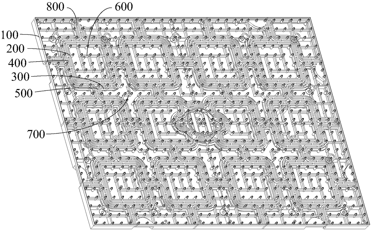
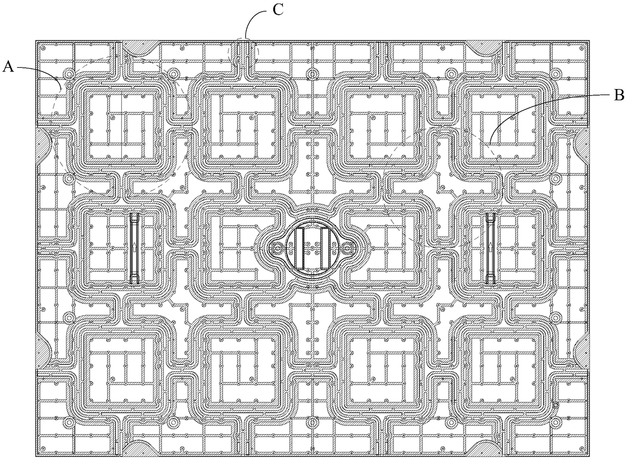
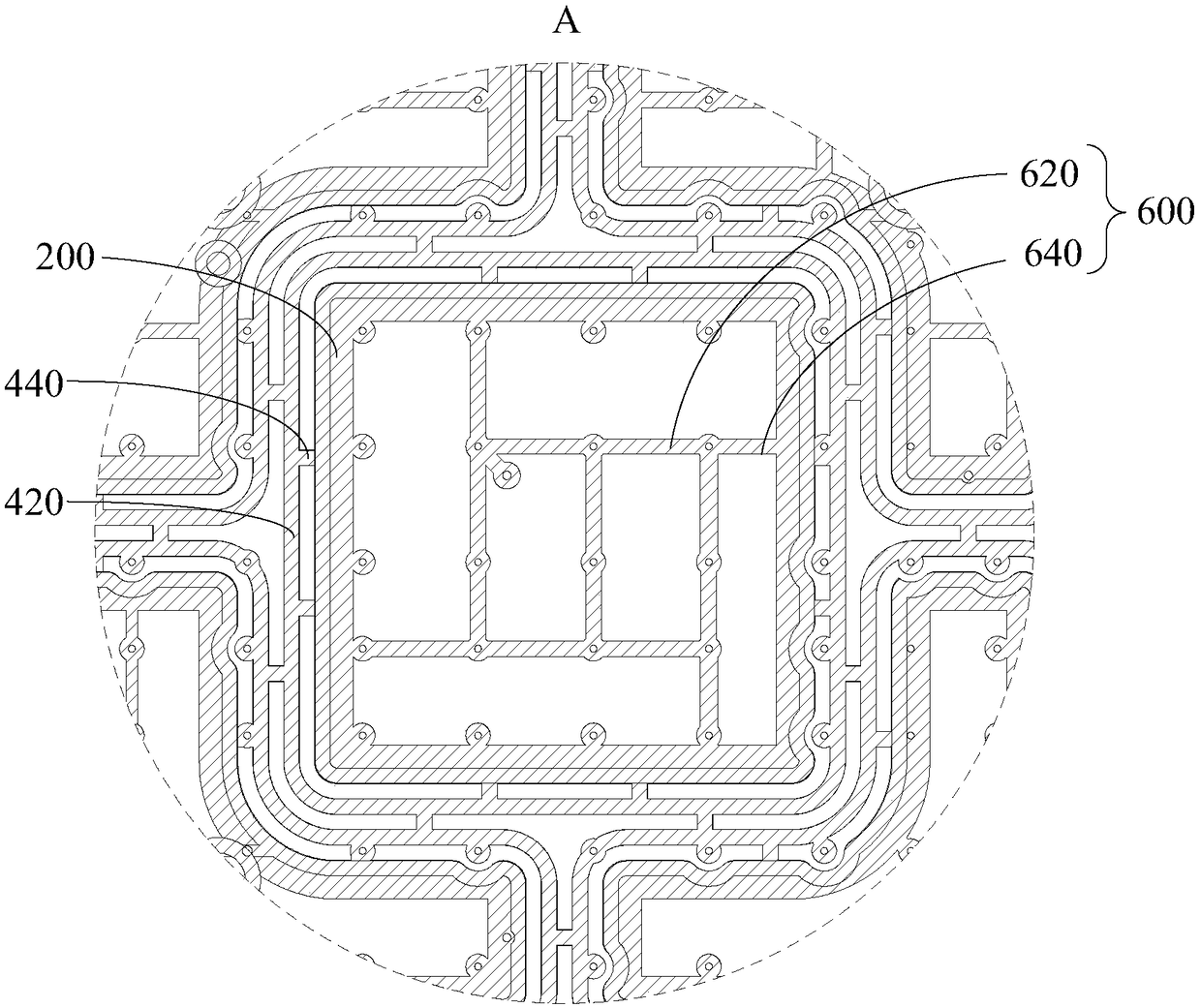
[0030] Such as Figure 1 to Figure 5 as shown, figure 1 It is a three-dimensional structural schematic diagram of an embodiment of the bottom case of the display device of the present invention; figure 2 for figure 1 The schematic diagram of the cross-sectional structure of the bottom shell shown; image 3 for figure 2 Partial enlarged schematic diagram of A; Figure 4 for fi...


PUM


Abstract

The invention discloses a bottom case of a display device, which comprises an outer edge and a plurality of first rigid structures, a second rigid structure, a first elastic structure and a second elastic structure arranged in the outer edge; the first rigid structures are arranged in rows at intervals; the second rigid structures are arranged in rows and staggered with the first rigid structure;a first elastic structure ring is arranged at the periphery of the first rigid structure and is used for absorbing the deformation amount generated by the expansion and contraction of the first rigidstructure; a second elastic structure ring is arranged at the periphery of the second rigid structure and is used for absorbing the deformation amount generated by the expansion and contraction of thesecond rigid structure. In the technical scheme of the invention, the expansion and contraction amount of the first rigid structure is absorbed by the first elastic structure; the expansion and contraction amount of the second rigid structure is absorbed through the second elastic structure, so that the external dimension of the case is effectively ensured, and the assembly effect of the bottom case and the display module is ensured.

Description

technical field [0001] The invention relates to the technical field of display devices, in particular to a bottom case of a display device. Background technique [0002] When the external temperature changes, especially in the process of turning on and off the display module, the display module with a small thermal expansion coefficient and the bottom case with a large thermal expansion coefficient will have a certain dimensional difference in the process of thermal expansion and contraction. value, that is, deformation incongruity. When the size of the display module is small, the difference has little effect on the flatness and structural stability of the display, but when its size exceeds a certain value (400mm), the difference can cause the module to bend, and the combination of the two The structure of the part is deformed and loosened, or even fails and falls off. [0003] In order to deal with the problems of display module bending and structural failure (such as lo...

Claims


Application Information

Patent Timeline
IPC IPC(8): G09F9/00H05K5/02
CPCG09F9/00H05K5/0217
Inventor 贺金锋康鹏飞
Owner UNILUMIN GRP
Learn More