
Top cover assembly and secondary battery

A technology of secondary battery and top cover, applied in the direction of secondary battery, secondary battery manufacturing, battery cover/end cover, etc., can solve the problem of affecting the assembly efficiency of secondary battery, complicated assembly process, and separation of pole and top cover. connection problems

Pending Publication Date: 2018-12-07
CONTEMPORARY AMPEREX TECH CO
View PDF0 Cites 7 Cited by
  • Summary
  • Abstract
  • Description
  • Claims
  • Application Information

AI Technical Summary

Problems solved by technology

[0004] Due to the complex structure of the pole itself and the assembly process, it will not only affect the assembly efficiency of the secondary battery, but after the pole is fixed on the top cover, the pole will often be disconnected from the top cover due to insufficient fixing force. phenomenon, thereby reducing the reliability of the secondary battery

Method used


Image

  • Top cover assembly and secondary battery
  • Top cover assembly and secondary battery
  • Top cover assembly and secondary battery

Examples


no. 1 example

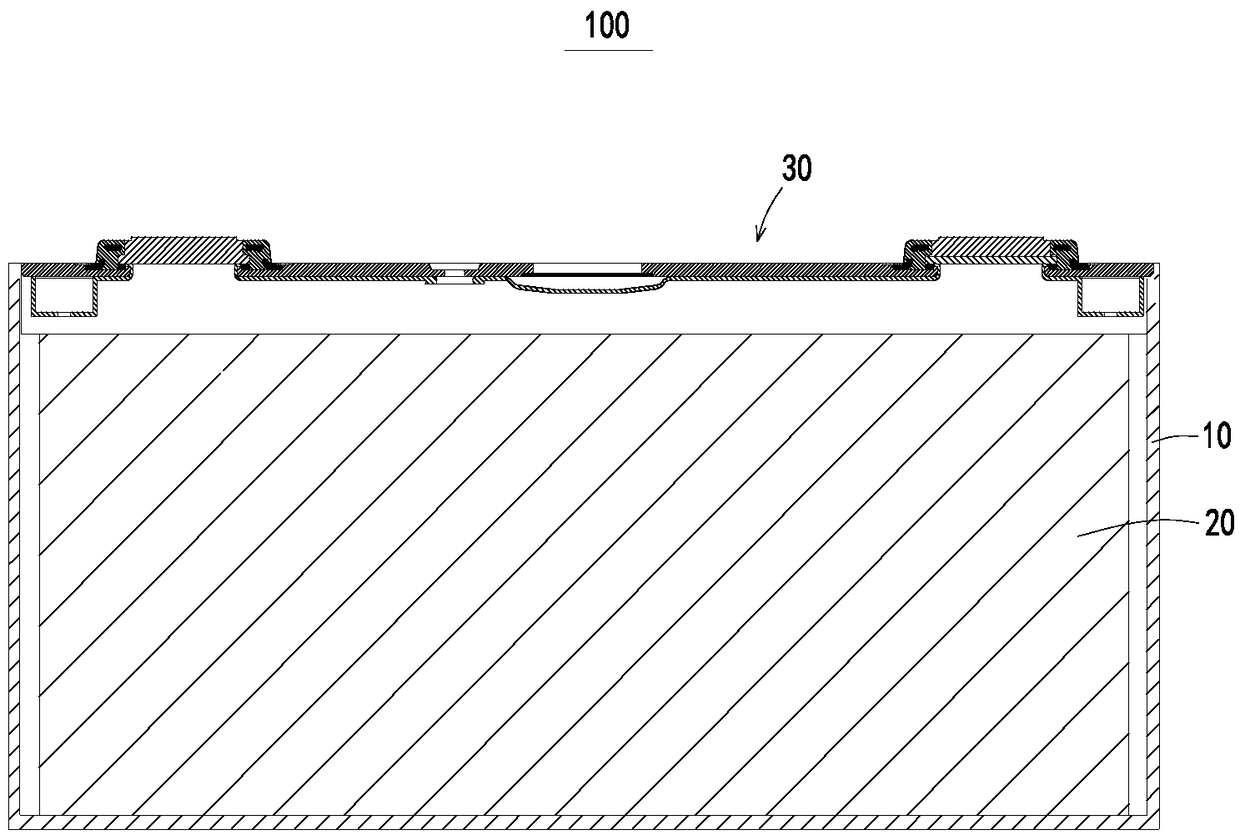
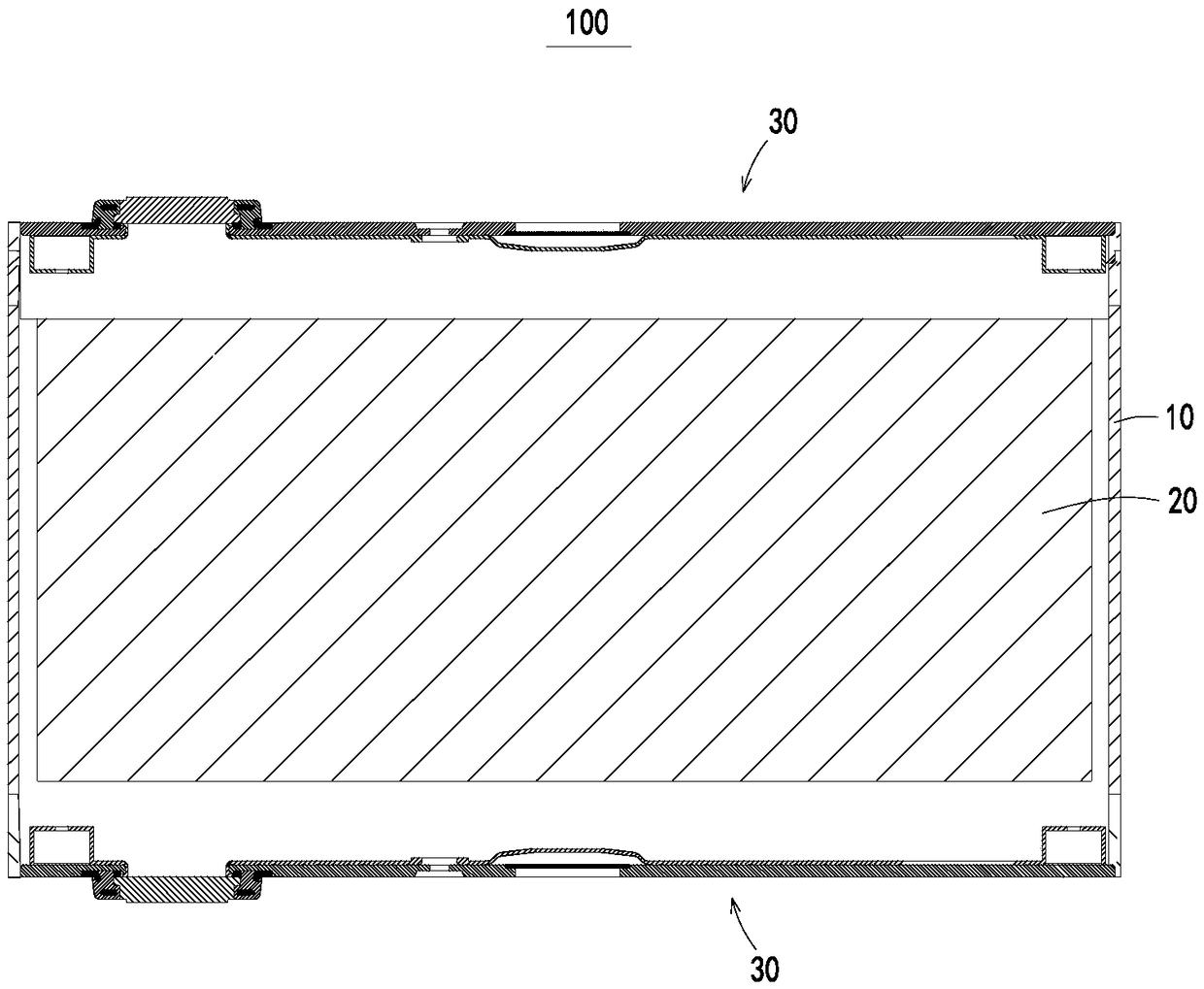
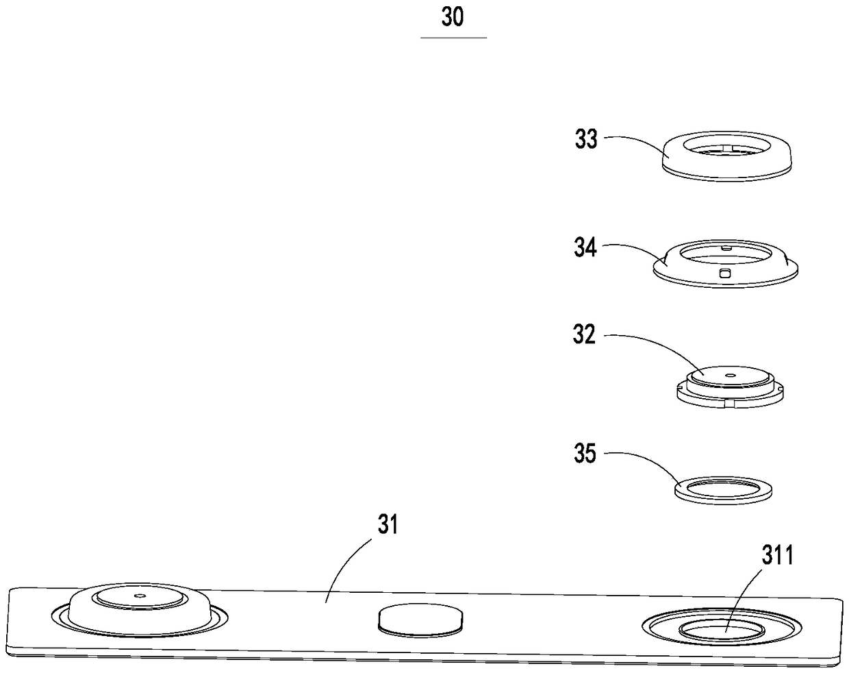
[0053] In order to better understand the present invention, the following combination Figure 3 to Figure 9 The secondary battery 100 and the top cover assembly 30 of the embodiment of the present invention will be described in detail.

[0054] see Figure 6 and Figure 7 As shown, the first fixing member 33 of this embodiment is provided with an embedding portion 331 , and the main body portion 341 of the second fixing member 34 is provided with an embedding hole 342 . A part of the first fixing member 33 is located in the embedding hole 342 to form the embedding portion 331 . The first fixing part 33 can effectively improve the connection strength between the first fixing part 33 and the second fixing part 34 through the embedded part 331 and the embedding hole 342 included in the second fixing part 34. The connection between the fixing part 33 and the second fixing part 34 is not easy to be separated or loosened, which further ensures the stability of the connection betw...

no. 2 example

[0068] In the first embodiment, the structure of the top cover assembly 30 has been described. In this embodiment, differences from the first embodiment are mainly described, and the same structure will not be repeatedly described in this embodiment.

[0069] see Figure 10 As shown, the first fixing member 33 of the embodiment of the present invention is provided with an embedding hole 342 , and the main body portion 341 included in the second fixing member 34 is provided with an embedding portion 331 . The embedding hole 342 provided on the first fixing member 33 may be a through hole or a blind hole. Preferably, the embedding hole 342 provided on the first fixing member 33 is a blind hole. A part of the second fixing member 34 is located in the embedding hole 342 to form the embedding portion 331 . The second fixing part 34 can effectively improve the connection strength between the first fixing part 33 and the second fixing part 34 through the embedded part 331 and the ...


PUM


Abstract

The invention relates to a top cover assembly and a secondary battery. The top cover assembly comprises: a top cover plate having an electrode lead-out hole, an electrode terminal including a terminalplate which is located at one side of the top cover plate, covers the electrode lead-out hole and has the outer peripheral surface protruding from the inner wall of the electrode lead-out hole, a first fixing member which at least partially surrounds the terminal plate to fix the electrode terminal to the first fixing member, and a second fixing member which is connected to the top cover plate, comprises a main body part and is separated from the electrode terminal through the first fixing member, wherein one of the first fixing member and the main body part is provided with an insertion holeand the other one of the first fixing member and the main body part is provided with an insertion part inserted into the insertion hole. The terminal plate in the top cover assembly is firmly fixed to the top cover plate through the first and second fixing members so that the separation of the terminal plate and the top cover plate is avoided and the structural safety of the secondary battery isimproved.

Description

technical field [0001] The invention relates to the technical field of batteries, in particular to a top cover assembly and a secondary battery. Background technique [0002] New energy vehicles are being widely promoted at home and around the world, but there are still many things to improve in order to completely replace fuel vehicles. For example, the mileage of the car is small, the cost of the battery pack is high, and the reliability of the battery pack needs to be further resolved. Based on the above problems, higher requirements are put forward for the secondary battery, which is the core part of electric vehicles, such as the need for the secondary battery to achieve higher energy density and lower cost. [0003] At present, the secondary battery generally adopts a square hard shell structure. The secondary battery shell includes a shell and a top cover assembly. The secondary battery shell provides a closed space for the electrode assembly and electrolyte, and the...

Claims


Application Information

Patent Timeline
IPC IPC(8): H01M2/04H01M2/26H01M10/04H01M50/147H01M50/172H01M50/50H01M50/531H01M50/548H01M50/55H01M50/552
CPCH01M10/04H01M50/55H01M50/548H01M50/147H01M50/552H01M50/50H01M50/172Y02E60/10Y02P70/50H01M10/049
Inventor 白璐璐郑于炼王鹏郭志君邢承友杨剑雄蔡其昌
Owner CONTEMPORARY AMPEREX TECH CO
Learn More