Data compression and decompression method, system and electronic equipment

A data compression and decompression technology, which is applied in transmission systems, electrical components, etc., can solve the problems of increasing equipment costs and hardware time-consuming, and achieves the effects of less resource occupation, simple implementation, and reduced compression loss

Active Publication Date: 2018-12-07
RUN TECH CO LTD BEIJING
View PDF6 Cites 4 Cited by
  • Summary
  • Abstract
  • Description
  • Claims
  • Application Information

AI Technical Summary

Problems solved by technology

When the optical fiber cannot meet the transmission needs, changing the hardware is not only time-consuming, but also increases the cost of the equipment

Method used


Image

  • Data compression and decompression method, system and electronic equipment
  • Data compression and decompression method, system and electronic equipment
  • Data compression and decompression method, system and electronic equipment

Examples


Embodiment 1

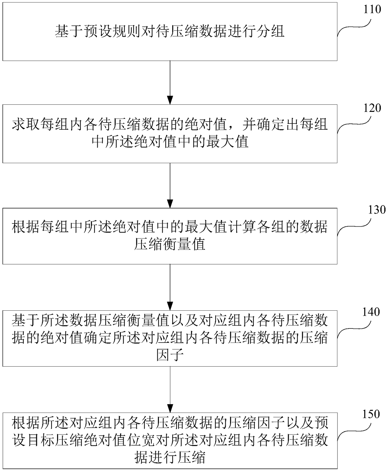
[0082] figure 1 It is a schematic flowchart of a data compression method provided by Embodiment 1 of the present invention. The data compression method of this embodiment is applied to the data sending end, and the data is compressed before sending the data, so as to reduce the requirement on the transmission capacity of the optical fiber. The data compression method can be executed by a sending module in the data compression system, the sending module can be implemented by software and / or hardware, and is generally integrated in the base station equipment. For details, see figure 1 As shown, the method may include the following steps:

[0083] 110. Group the data to be compressed based on a preset rule.

[0084] Wherein, the data to be compressed may specifically refer to IQ data bidirectionally transmitted between the BBU and the RRU in the TD-LTE base station equipment through an optical fiber.

[0085] Exemplarily, the data to be compressed is grouped based on preset r...

Embodiment 2

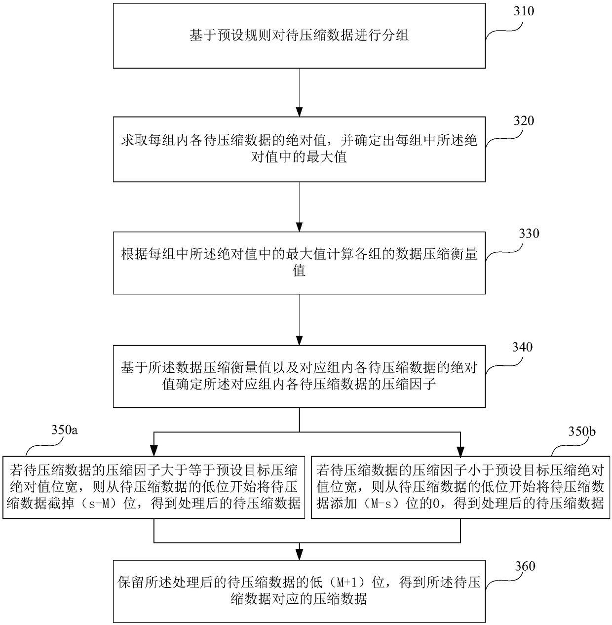
[0106] image 3 It is a schematic flowchart of a data compression method provided by Embodiment 2 of the present invention. On the basis of the above embodiments, this embodiment optimizes the data compression process by way of example. The advantage of optimization is that the compression process is simplified, so that Compression is easier to implement, without using complex hardware devices, and takes up less system resources. For details, see image 3 As shown, the method includes:

[0107] 310. Group the data to be compressed based on a preset rule.

[0108] 320. Obtain the absolute value of each data to be compressed in each group, and determine a maximum value among the absolute values ​​in each group.

[0109] 330. Calculate the data compression metrics of each group according to the maximum value of the absolute values ​​in each group.

[0110] 340. Determine a compression factor of each data to be compressed in the corresponding group based on the data compressio...

Embodiment 3

[0129] Figure 6 It is a schematic flowchart of a data decompression method provided by Embodiment 3 of the present invention. The data decompression method in this embodiment is applied to a data receiving end to decompress the compressed data in the above embodiments. The data decompression method can be executed by a receiving module in the data compression system, the receiving module can be implemented by software and / or hardware, and is generally integrated in the base station equipment. For details, see Figure 6 As shown, the method may include the following steps:

[0130] 610. Determine the compression factor of the data to be compressed according to the received identification bit of the data to be compressed and the reference factor of the group to which the data to be compressed belongs.

[0131] Specifically, if the identification bit of the data to be compressed is 1, the compression factor of the data to be compressed is k;

[0132] If the identification bi...


PUM


Abstract

The embodiment of the invention discloses a data compression and decompression method, system, and electronic equipment. The data compression method comprises the following steps: grouping to-be-compressed data based on a preset rule; solving an absolute of each to-be-compressed data in each group, and determining the maximum value in the absolute values in each group; computing the data compression measurement value of each group according to the absolute value in each group; determining a compression factor of each to-be-compressed data in the corresponding group based on the data compression balance value and the absolute value of each to-be-compressed data in the corresponding group; and compressing each to-be-compressed data in the corresponding group according to the compression factor of each to-be-compressed data in the corresponding group and the preset target compression absolution value bit width. By adopting the above technical scheme disclosed by the invention, the IQ datacan be effectively compressed, the compression loss of small signal is reduced, and the compression performance is improved.

Description

technical field [0001] The embodiments of the present invention relate to the technical field of mobile communication, and in particular to a data compression and decompression method, system and electronic equipment. Background technique [0002] In the mobile communication system, the TD-LTE base station is a distributed base station equipment, including BBU (Base BaMdUMit, base band unit) and RRU (Remote RF UMit, radio frequency remote unit), BBU and RRU are connected by optical fiber, bidirectional The IQ data is transmitted, and the IQ data is a baseband digital signal, including an I channel signal and a Q channel signal. [0003] With the development of mobile communication technology, high-speed and large-capacity data transmission is an inevitable trend. The increase in the amount of data also puts forward higher requirements on the optical fiber data transmission capability of the base station. At the same time, higher-speed optical modules are required, and the c...

Claims


Application Information

Patent Timeline
Patent Type & Authority Applications(China)
IPC IPC(8): H04L29/06
CPCH04L69/04
Inventor 火一莽韩洁万月亮
Owner RUN TECH CO LTD BEIJING
Why Eureka
Try Eureka