A physical desuperheater

A technology of physical cooling and cooling devices, which is applied to heating appliances for treatment, cooling appliances for treatment, contraceptives, etc. It can solve problems such as poor cooling effect, waste of water resources, and risk of water leakage and water seepage. Poor cooling effect, good cooling effect

Active Publication Date: 2018-12-11
金湖县华瑞医疗器械有限公司
View PDF6 Cites 1 Cited by
  • Summary
  • Abstract
  • Description
  • Claims
  • Application Information

AI Technical Summary

Problems solved by technology

[0006] (1) The cooling effect of the existing design is not good, and the problem of wasting water resources;
[0007] (2) The existing design of the water pipe joints has not been specially treated, and there is a risk of water leakage;
[0008] (3) The existing design can only be used independently, and cannot carry out large-scale cooling work

Method used


Image

  • A physical desuperheater
  • A physical desuperheater
  • A physical desuperheater

Examples


Embodiment 1

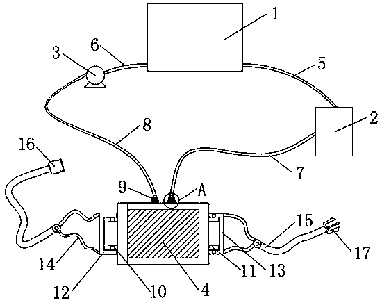
[0033] see Figure 1-3 , a physical cooler, comprising a water storage tank 1, a refrigerator 2, a circulation pump 3 and a cooling device 4, characterized in that: a first communication pipe 5 is arranged between the refrigerator 2 and the water storage tank 1, and the two ends of the first communication pipe 5 The ends are connected with the refrigerator 2 and the water storage tank 1 respectively, and a second communication pipe 6 is arranged between the circulation pump 3 and the water storage tank 1, and the two ends of the second communication pipe 6 are respectively connected with the refrigerator 2 and the water storage tank 1, and the refrigerator 2 is also fixedly connected with a water inlet pipe 7, the cooling device 4 is connected with the end of the water inlet pipe 7 away from the refrigerator 2, and the circulating pump 3 is also fixedly connected with a water outlet pipe 8, and the cooling device 4 is connected with the end of the water outlet pipe 8 away from ...

Embodiment 2

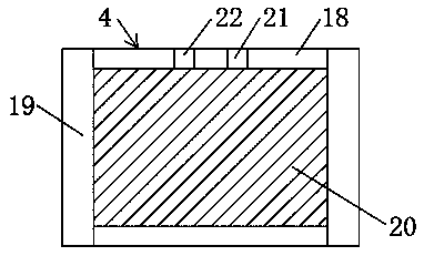
[0036] Example 2: See Figure 4 , based on Embodiment 1 or the same as Embodiment 1, the difference is that the sealing joint 9 includes a fixed seat 27, a spiral sleeve 29 and a movable pipe 31, and the fixed seat 27 is fixedly connected with the water inlet hole 21 on the rubber strip 18 , the fixed seat 27 is fixedly connected with a threaded pipe 28, the spiral sleeve 29 is spirally connected with the spiral pipe 28, the inside of the spiral sleeve 29 is provided with a mounting groove 30, the movable pipe 31 is slidingly connected with the mounting groove 30, and the bottom surface of the movable pipe 31 The top is fixedly connected with a sealing ring 32, and the end of the movable pipe 31 away from the sealing ring 32 is fixedly connected with the water inlet pipe 7. The movable pipe 31 is also sleeved with a connecting ring 33, and a first spring is arranged between the connecting ring 33 and the movable pipe 31. 34. One end of the first spring 34 is fixedly connected ...

Embodiment 3

[0038] Example 3: Please refer to Image 6 , based on Embodiment 1 or the same as Embodiment 1, the difference is that the fixing device includes a first connecting buckle 12 and a second connecting buckle 13, and the first connecting buckle 12 and the second connecting buckle 13 are fixedly connected with a connecting belt 14. The connecting belt 14 is fixedly connected to the elastic strap 15, the end of the elastic strap 15 away from the first connecting buckle 12 is fixedly connected to the snap sleeve 16, and the end of the elastic strap 15 away from the second connecting buckle 13 is fixedly connected to the buckle 17.

[0039] The connecting frame 10 is provided with a first connecting hole, the first connecting buckle 12 is fixedly connected with the second protruding rod, the second protruding rod matches the first connecting hole, and the second connecting buckle 13 is provided with a second connecting hole , the second connecting hole is matched with the first protr...


PUM


Abstract

The invention discloses a physical desuperheater, belonging to the technical field of desuperheaters. The physical desuperheater consists of a water storage tank, a thermoelectric cooler, a circulation pump, and a cooling device. The first communication tube is arranged between the thermoelectric cooler and the water storage tank. The second communication tube is arranged between the circulation pump and the water storage tank. A water inlet pipe is connected fixedly to the thermoelectric cooler. The cooling device is connected to the end of the water inlet pipe away from the thermoelectric cooler. The circulation pump is also connected fixedly to a water outlet pipe. The cooling device is connected to the end of the water outlet pipe away from the circulation pump. A seal fitting is provided at the connection between the cooling device and the water inlet and outlet pipe; When in use, the circulating water system in the cooling devices in the water storage tank can be achieved by using the circulation pump, thereby saving water resources. In addition, the water temperature can be effectively lowered by the setting on the thermoelectric cooler, so a better cooling effect is achieved. By using the design, the problem of poor cooling effect and the waste of water resources in the existing design is effectively solved.

Description

technical field [0001] The invention relates to the technical field of cooling devices, in particular to physical cooling devices. Background technique [0002] When the hospital treats critically ill patients with high fever and drugs are ineffective, physical methods are used to reduce the temperature, such as alcohol rubbing and ice compresses, etc. Alcohol is irritating to the skin and cannot be used for trauma. The temperature difference between ice and human body is very large and it will melt into water to pollute the environment without careful care It is easy to cause frostbite, and the prior art has not yet made a good solution to the above-mentioned problems, so it is very necessary to design a physical cooler that can solve the above-mentioned problems. [0003] At present, the existing physical coolers on the market are directly connected to the water source, and use the water to flow in the water bag to achieve the purpose of cooling. Although this design does ...

Claims


Application Information

Patent Timeline
Patent Type & Authority Applications(China)
IPC IPC(8): A61F7/00
CPCA61F7/00A61F2007/0056
Inventor 郑宝华郑超
Owner 金湖县华瑞医疗器械有限公司
Why Eureka
Try Eureka