Novel low-resistance injector

A low-resistance syringe and syringe technology, applied in the field of medical devices, can solve the problems of high resistance of the syringe, difficulty in using up the liquid medicine, and one-time use, etc., and achieve the effects of reducing pain, saving production costs, and uniform output

Pending Publication Date: 2018-12-11
四川普瑞斯生物科技有限公司
View PDF9 Cites 0 Cited by
  • Summary
  • Abstract
  • Description
  • Claims
  • Application Information

AI Technical Summary

Problems solved by technology

[0005] The purpose of the present invention is to provide a novel low-resistance syringe, which can solve the defects of excessive resistance and labor-intensive and time-consuming use of the syringe in the prior art, and it can also solve the problem that the drug solution is difficult to use up when the syringe is administered in the prior art. problem, it can also solve the problem in the prior art that some special syringes can only be used as a whole

Method used


Image

  • Novel low-resistance injector
  • Novel low-resistance injector
  • Novel low-resistance injector

Examples


specific Embodiment 1

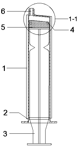
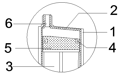
[0041] The novel low-resistance syringe of the present embodiment combines Figure 1~5 As shown, it includes a syringe outer sleeve 1, a syringe inner sleeve 2 and a core rod 3 installed in the syringe inner sleeve 2. The syringe outer sleeve 1 can be placed on the syringe inner sleeve 2, and the top of the syringe outer sleeve 1 is provided with a feed liquid outlet. The liquid injection cone 6 at the top of the inner sleeve 2 of the syringe can extend out of the outer sleeve 1 of the syringe through the outlet of the feed liquid, and the top end of the inner sleeve 2 of the syringe is inclined; the core rod 3 includes a rod head and a shaft, and the rod The head and the rod body are detachably connected, and the rod head includes a rubber plug 5 and an annular rubber ring 4. The shape of the upper end surface of the rubber plug 5 is consistent with the shape of the upper end of the inner sleeve of the syringe 2. An annular groove matching the ring-shaped rubber ring 4. The r...

specific Embodiment 2

[0046] The difference from Embodiment 1 is that the combination Figure 1~5 and Figure 7 As shown, in the novel low-resistance syringe of this embodiment, the upper end of the shaft is provided with a snap ring 7, and the lower end of the shaft head is provided with a card slot 8, and the shaft head is snap-connected with the shaft body. The end surface can be provided with a protruding column, and a snap ring 7 is arranged around the protruding column, and a groove with an internal thread 22 is provided on the lower end surface of the rod head, and the external thread 21 of the protruding column matches the internal thread 22 of the groove.

[0047] Wherein, the rubber plug 5 can be made of medical rubber material, and the protruding column can also be made of medical rubber material.

[0048] In the usual injection process, the core rod 3 hardly touches the liquid medicine, and the rubber plug 5 and the core rod 3 are discarded together after use, which is very wasteful. ...

specific Embodiment 3

[0049] Different from the second specific embodiment, the combination of Figure 1~6 As shown, in the novel low-resistance syringe of this embodiment, the upper end of the shaft is provided with an external thread 21, and the lower end of the shaft is provided with an internal thread 22, and the shaft head is threadedly connected to the shaft. Specifically, the upper end surface of the shaft is A protruding post can be provided, and an external thread 21 can be provided around the protruding post, and a groove with an internal thread 22 is provided on the lower end surface of the rod head, and the external thread 21 of the protruding post matches the internal thread 22 of the groove.

[0050] Wherein, the protruding column can also be made of medical rubber material.

[0051] Through the thread connection, the structure of the connection between the shaft and the thread is simple, the operation is fast and convenient, and it is helpful to improve the work efficiency.


PUM


Abstract

The invention provides a novel low-resistance injector which comprises an injector outer sleeve, an injector inner sleeve and a core rod mounted in the injector inner sleeve. The core rod comprises arod head and a rod body which are in detachable connection, the top end of the injector inner sleeve is in the shape of a bevel and is identical with the upper end face of a rubber plug in shape, andthe rubber plug can sufficiently push medicinal liquid out from a liquid outlet at the upper end of the injector inner sleeve; an annular groove matched with an annular rubber ring is arranged on therubber plug, and the edge of the annular rubber ring is close to the inner side wall of the injector inner sleeve and protrudes out of a rubber plug body when sleeving in the annular groove. Resistance can be further reduced through movement in this way, and certain damping effect can be realized. Through structural improvement, the injector is more convenient for medical staff to operate, so thatmedicine liquid utilization rate is increased; the injector is simple in structure, so that production cost is lowered to a certain degree.

Description

technical field [0001] The invention belongs to the technical field of medical devices, in particular to a novel low-resistance syringe. Background technique [0002] A syringe is a common medical appliance. The syringe consists of a needle barrel with a small hole at the front end and a matching piston core rod. It is used to inject a small amount of liquid into or withdraw it from areas that are inaccessible by other methods. When the core rod is pulled out, the liquid or gas is sucked from the small hole at the front end of the syringe, and the liquid or gas is squeezed out when the core rod is pushed in. [0003] At present, the syringe is generally composed of an outer sleeve, an inner sleeve, a core rod, and a rubber plug. In order to ensure the sealing performance of the product, the rubber plug at the sealing part of the general solid rubber plug is often displayed relatively wide, and the wide rubber plug will increase the use time of the product accordingly. The f...

Claims


Application Information

Patent Timeline
Patent Type & Authority Applications(China)
IPC IPC(8): A61M5/178A61M5/31A61M5/315
CPCA61M5/178A61M5/3129A61M5/31511
Inventor 雷冰
Owner 四川普瑞斯生物科技有限公司
Why Eureka
Try Eureka