A system and method for external power supply of a mobile charging vehicle

A technology of mobile charging and power supply system, which is applied in electric vehicle charging technology, motor vehicles, electric vehicles, etc., and can solve problems such as damage to electric vehicles, long charging time, and limited service capabilities of mobile charging vehicles

Active Publication Date: 2018-12-11
宁波洁程汽车科技有限公司
View PDF6 Cites 12 Cited by
  • Summary
  • Abstract
  • Description
  • Claims
  • Application Information

AI Technical Summary

Problems solved by technology

If the electric energy is exhausted before arriving at the charging station, it is generally costly and inconvenient to ask a tow truck to tow the electric vehicle to the charging station. The towing process may also cause damage to the electric vehicle
[0004] In order to solve the problem that electric vehicles cannot move due to exhaustion of electric energy before reaching the charging station, someone designed a mobile charging vehicle, which is constructed by loading a large number of rechargeable batteries in the vehicle body, and configuring a power distribution system and a charging gun to form a mobile energy-carrying battery for charging. The power distribution system realizes emergency charging of electric vehicles without power. The existing electric vehicles are equipped with a battery parameter detection module for real-time detection of the rated charging power and remaining power of the charged vehicle3
[0005] However, due to the limitation of the load capacity of the current mobile charging vehicle, and the low energy density of the battery used for service, the charging time is long and the cost is high, which greatly limits the service capability of the mobile charging vehicle, and there is still room for improvement.

Method used


Image

  • A system and method for external power supply of a mobile charging vehicle
  • A system and method for external power supply of a mobile charging vehicle
  • A system and method for external power supply of a mobile charging vehicle

Examples


Embodiment 1

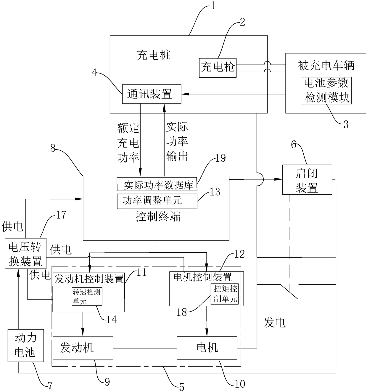
[0045] Such as figure 1As shown, the external power supply system of the mobile charging vehicle includes a charging pile 1. The function of the charging pile 1 is similar to that of a fuel dispenser in a gas station. The charging pile 1 here is installed on the mobile charging vehicle, and can be used for various Model electric car charging, charging pile 1 is provided with charging gun 2, in order to be inserted in the charged vehicle by charging gun 2 to carry out power supply when needed.

[0046] The charged vehicle is provided with a battery parameter detection module 3 for real-time detection of the rated charging power and remaining power of the charged vehicle. The battery parameter detection module 3 is similar to the battery management system. The charging pile 1 is provided with a battery parameter detection module for receiving 3. A communication device 4 for the detected data, wherein the communication device 4 is preferably a communication board.

[0047] The p...

Embodiment 2

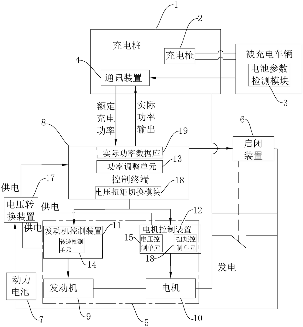
[0056] Such as figure 2 As shown, different from embodiment 1, the power battery 7 is disconnected after the engine 9 enters idle speed in embodiment 2, which is specifically described as follows:

[0057] The external power supply system of the mobile charging vehicle also includes a rotational speed detection unit 14 arranged on the engine control device 11 for detecting the rotational speed of the engine 9, an actual power database 19 that stores the actual power and the corresponding rated rotational speed of the engine 9 and the rated torque of the motor 10 ;

[0058] If the rotational speed detected by the rotational speed detection unit 14 reaches the rotational speed preset by the control terminal 8 under the idling state of the engine 9, the control terminal 8 stops the electric energy supplied by the power battery 7 to the opening and closing device 6, and simultaneously uses the feedback from the power adjustment unit 13 The actual power is the query object in the...

Embodiment 3

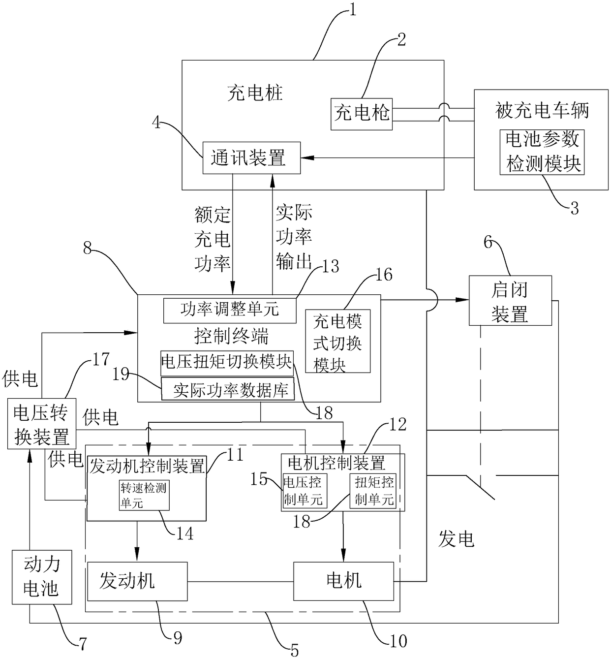
[0067] Such as image 3 As shown, different from Embodiment 2, on the basis of Embodiment 2, the control terminal 8 also includes a charging mode switching module 16. Since the conversion rate of the engine 9 is low, when the required power of the charged vehicle is less; if The remaining power obtained by the interactive communication between the control terminal 8 and the communication device 4 reaches the preset charging mode switching value, and the charging mode switching module 16 is activated to make the power battery 7 supply power to the opening and closing device 6 again and at the same time the control terminal 8 controls the engine 9 to control The device stops the engine 9 to ensure that the power battery 7 and the motor 10 supply power to the charging pile 1 at the same time until the charged vehicle is fully charged.

[0068] The above is the description of the external power supply system of the mobile charging vehicle, and the following is a further descriptio...


PUM


Abstract

The invention discloses a system for external power supply of a mobile charging vehicle, and relates to the field of charging of electric vehicles. which solves the problem that the mobile charging vehicle is limited in load capacity at present, and the energy density of the battery loaded for service is low, the charging time is long, the cost is high, which greatly limits the service capabilityof mobile charging vehicles. The main points of the technical scheme are as follows: includes a communication device arranged in a charging pile for receiving data detected by a battery parameter detection module, an electric power supply, an opening / closing device for controlling whether or not an electric power supply device is supplied with electric power, a power battery which is supplied to an opening and closing device, and a control terminal which is in interactive communication with a communication device and is used for distributing the power of the power battery to the opening and closing device and for controlling the power supply device.The invention relates to a mobile charging vehicle external power supply system, which shortens the charging period, has low cost, high energystorage and improves the power supply efficiency.

Description

technical field [0001] The invention relates to the field of electric vehicle charging, in particular to an external power supply system and method for a mobile charging vehicle. Background technique [0002] At present, pure electric vehicles and plug-in hybrid vehicles are being rapidly industrialized, and vertical charging piles and wall-mounted charging devices have become popular. Due to their fixed positions, they can only meet the fixed-point charging needs of vehicles. [0003] In real life, it often happens that electric vehicles cannot continue to drive because the electric energy stored in the power battery is exhausted because they do not reach the charging station. If the electric energy has been exhausted before arriving at the charging station, it is generally costly and inconvenient to ask a tow truck to tow the electric vehicle to the charging station, and the towing process may also cause damage to the electric vehicle. [0004] In order to solve the probl...

Claims


Application Information

Patent Timeline
Patent Type & Authority Applications(China)
IPC IPC(8): B60P3/00B60L11/18B60L11/12
CPCB60P3/00Y02T10/70Y02T10/7072Y02T90/12Y02T90/16
Inventor 孙强熊文羽冯瀚张晓燕
Owner 宁波洁程汽车科技有限公司
Why Eureka
Try Eureka