Portable assembled fan

A fan and fan blade technology is applied in the field of fans that are assembled and easy to carry. It can solve the problems of inconvenient disassembly, difficult cleaning and maintenance, and large volume, and achieve the effects of easy cleaning, reducing difficulty and ensuring cleanliness.

Inactive Publication Date: 2018-12-11
曹宇童
View PDF0 Cites 0 Cited by
  • Summary
  • Abstract
  • Description
  • Claims
  • Application Information

AI Technical Summary

Problems solved by technology

[0003] However, the fan blades and the drive motor of most fans on the market are integrated structures, which are inconvenient to carry due to their large volume, and most of the existing fan front covers and fan rear covers are fixed by bolts. As a result, if you need to clean the inside of the fan, you need to use a screwdriver to disassemble the fan front cover and fan rear cover, which is inconvenient to disassemble and makes cleaning and maintenance more difficult

Method used


Image

  • Portable assembled fan
  • Portable assembled fan
  • Portable assembled fan

Examples


Embodiment 1

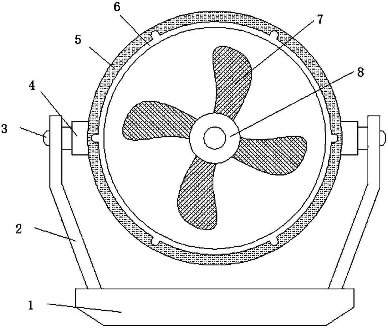
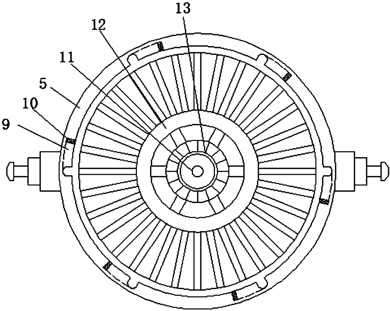
[0027] Embodiment one, with reference to Figure 1-4 , a combined assembled and portable fan, including a bracket bottom plate 1, two side risers 2 are symmetrically welded on the upper surface of the bracket bottom plate 1, and a fan back cover is connected between the two side risers 2 through a rotating pin 4 5. A motor fixing frame 12 is welded at the center of the front surface of the fan rear cover 5, and a driving motor 13 is welded at the center of the motor fixing frame 12. One end of the driving motor 13 is welded with a rotating shaft 11, and one end of the rotating shaft 11 is clamped with a fan blade. Mounting plate 8, fan blade 7 is welded on the outer wall of fan blade mounting plate 8, fan front cover 6 is clamped at the edge of the front surface of fan rear cover 5 through card slot 9, and the outer wall of fan front cover 6 is welded with a connection for use with card slot 9 There are four clamping plates 20 and four fixing pins 16 , and the four fixing pins...

Embodiment 2

[0028] Embodiment two, refer to figure 1 and figure 2 , Fix between the two side vertical plates 2 and the rotating pin shaft 4 by the fixing bolt 3, the side vertical plate 2 can be separated from the rotating pin shaft 4 by dismounting the fixing bolt 3.

Embodiment 3

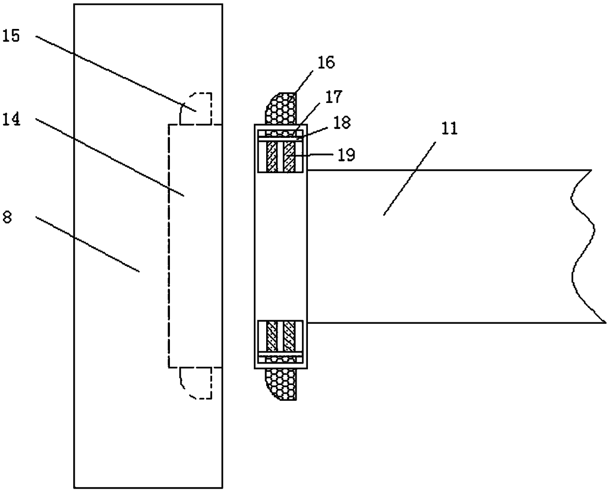
[0029] Embodiment three, refer to image 3 One side of the fan blade mounting plate 8 is provided with a connecting slot 14, and the inner wall of the connecting slot 14 is provided with a fixed pin groove 15, and the outer wall of one end of the rotating shaft 11 is provided with a mounting groove 17, and the inner wall of the mounting groove 17 is connected by an elastic member 19. There is a movable plate 18, one side of the movable plate 18 is welded with a fixed pin clamp 16, and the fixed pin clamp 16 is clamped in the fixed pin groove 15, when the fan blade mounting plate 8 is installed, only one end of the rotating shaft 11 needs to be Just insert it into the connection slot 14. Since the edge of the fixed pin card 16 is an arc-shaped structure, when the rotating shaft 11 is inserted into the connecting slot 14, the fixed pin card 16 on the rotating shaft 11 will automatically compress the elastic part 19, and shrink toward the inside of the rotating shaft 11 until the...


PUM


Abstract

The invention discloses a portable assembled fan, comprising a support bed plate. Two side vertical plates are welded onto the upper surface of the support bed plate symmetrically; a fan back hood isrotationally connected between the two side vertical plates through pivot pins; a motor holder is welded to the center of the front surface of the fan back hood and a drive motor is welded to the center of the motor holder; a rotation shaft is welded to one end of the drive motor, and a vane mounting plate is fastened to one end of the rotation shaft. The portable assembled fan is divided into four parts, namely the support bed plate, the fan front hood, the fan back hood and the vane mounting plate, the fan back hood is connected above the support bed plate through the pivot pins rotationally, the fan front hood is fastened to the front surface of the fan back hood through clamp plates, the vane mounting plate is fastened to one end of the rotation shaft on the fan back hood through a fixing pin, and thus, mounting difficulty is reduced, and combining, assembling and carrying of the fan are facilitated.

Description

technical field [0001] The invention relates to the field of fans, in particular to a combined and portable fan. Background technique [0002] Fan refers to a device used to generate wind to keep cool in hot weather. Electric fan is a device that is driven by electricity to generate air flow. The fan installed in it is energized and then rotated into natural wind to achieve the effect of cooling. The fan can be divided into: single motor structure Phase capacitor type, single-phase shaded pole type, three-phase induction type, DC and AC-DC dual-purpose series-excited commutator electric fans; according to the classification can be divided into: household electric fans and industrial exhaust fans; according to the air inlet and outlet classification can be Divided into: axial fan, centrifugal fan and cross flow fan, etc. With the development of technology and social progress, there are more and more types of fans, and people's requirements for fans are also getting higher and...

Claims


Application Information

Patent Timeline
IPC IPC(8): F04D25/08F04D29/64
CPCF04D25/08F04D29/646
Inventor 曹宇童
Owner 曹宇童
Why Eureka
Try Eureka