High-efficiency energy-saving burner nozzle

A combustion nozzle and energy-saving technology, which is applied in the field of two-fluid nozzles, can solve the problems of low combustion efficiency, insufficient atomization degree, and nozzles are prone to coking, and achieve the effect of improving combustion efficiency and improving atomization degree.

Pending Publication Date: 2018-12-11
洛阳帝博石化装备有限公司
View PDF14 Cites 0 Cited by
  • Summary
  • Abstract
  • Description
  • Claims
  • Application Information

AI Technical Summary

Problems solved by technology

After being put into production, when the traditional combustion nozzle with the above-mentioned structure is used for combustion operation, due to insufficient atomization, the combustion flame is red and coking is prone to occur at the outlet end of the nozzle, resulting in incomplete combustion and low combustion efficiency

Method used


Image

  • High-efficiency energy-saving burner nozzle
  • High-efficiency energy-saving burner nozzle

Examples


Embodiment Construction

[0027] In the following, a high-efficiency and energy-saving combustion nozzle proposed by the present invention will be further described with reference to the drawings and preferred embodiments.

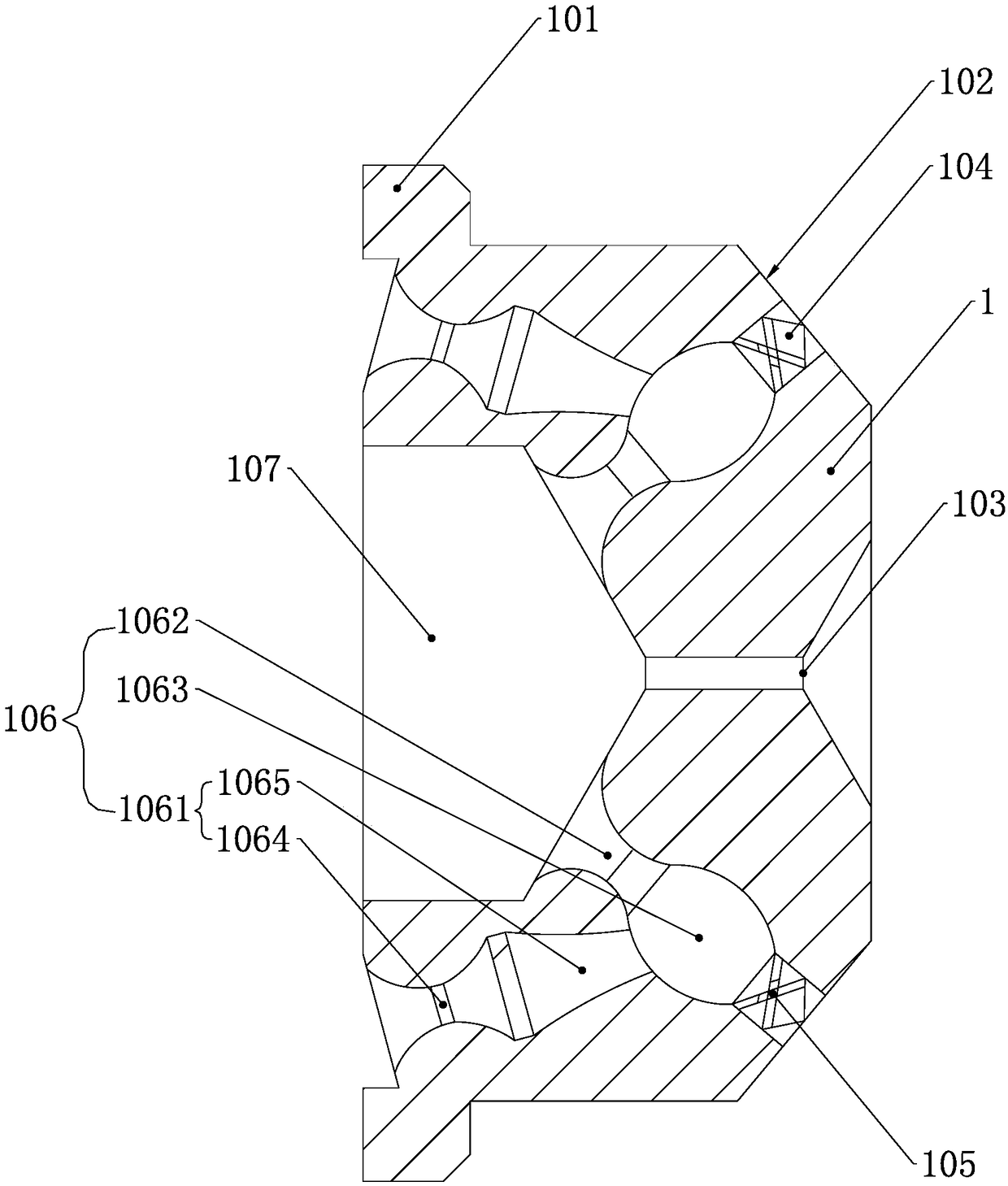
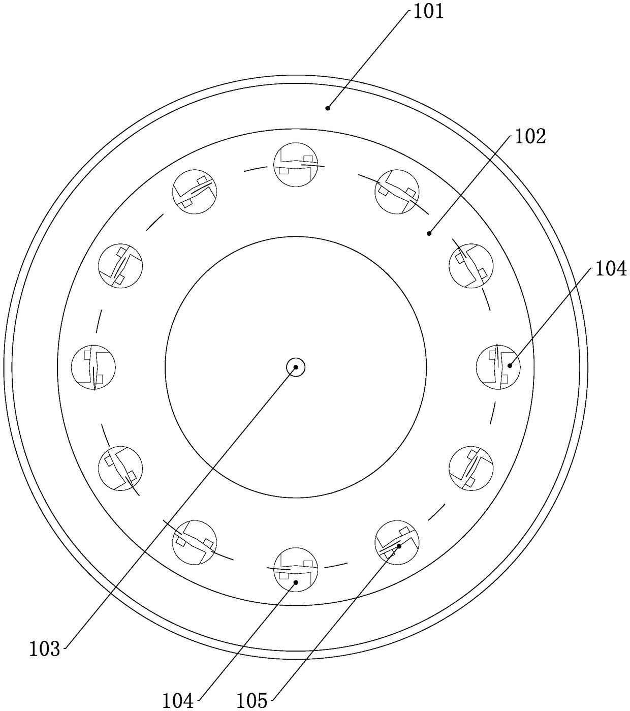
[0028] See figure 1 , figure 2 , A high-efficiency and energy-saving combustion nozzle, comprising a nozzle body 1, the inlet end of the nozzle body 1 is processed with a boss 101, the boss 101 is fixed to the gas-liquid conveying pipe (not shown) to facilitate liquid oil, gas Enter the nozzle body 1 respectively. The outlet end of the nozzle body 1 is processed with a chamfer 102, and the middle of the outlet end surface is provided with a liquid spray hole 103. The chamfer 102 is provided with 12 oil-gas mixing outlets 104 along the circumferential direction, and each oil-gas mixing outlet 104 A solid blade 105 is installed to ensure that a solid fog field is formed at each oil-gas mixing outlet.

[0029] The inside of the gas-liquid conveying pipe is provided with an oil passage a...


PUM


Abstract

The invention provides a high-efficiency energy-saving burner nozzle. The end face of an inlet of a nozzle body is provided with a liquid distribution groove. The end of an outlet of the nozzle body is chamfered. The middle portion of the end face of the outlet is provided with a liquid spray hole. The chamfer is uniformly provided with a plurality of oil-gas mixing outlets in the circumferentialcircumference. Solid blades are mounted in an outlet of each oil-gas mixing outlet. The nozzle body is internally provided with a plurality of oil-gas mixing channels with the same number as the oil-gas mixing outlets. Each oil-gas mixing channel comprises a gas channel, a liquid channel and a mixing cavity, wherein an inlet of the gas channel communicates with a gas passage, and an outlet of thegas channel communicates with the mixing cavity; an outlet of the liquid channel communicates with the mixing cavity; the mixing cavity communicates with the corresponding oil-gas mixing outlet. The liquid channels and the liquid spray hole communicate with the liquid distribution groove. The liquid distribution groove communicates with an oil passage. When the high-efficiency energy-saving burnernozzle is used for conducting burning operation, burning flames are blue, and the burning efficiency is improved by 80%-90%. Moreover, the coking phenomenon cannot occur to the outlet end of the nozzle.

Description

Technical field [0001] The invention relates to a two-fluid nozzle, in particular to a high-efficiency and energy-saving combustion nozzle. Background technique [0002] The combustion nozzle is a component that can atomize and spray liquid at high speed. The traditional combustion nozzle includes a gas-liquid conveying pipe, a nozzle body installed at the end of the gas-liquid conveying pipe, and a nozzle body installed at the other end of the gas-liquid conveying pipe. The oil inlet and the air inlet, the gas-liquid conveying pipe is provided with an oil passage communicating with the oil inlet along the axial direction, and the annular space formed by the oil passage and the inner wall of the gas-liquid conveying pipe serves as the air passage. The air ports are connected; a collision body is arranged in the nozzle body. The working process is as follows: the pressurized liquid oil enters the oil passage through the oil inlet, and the pressurized gas enters the air passage th...

Claims


Application Information

Patent Timeline
Patent Type & Authority Applications(China)
IPC IPC(8): F23D11/10F23D11/38
CPCF23D11/10F23D11/38
Inventor 百利翔
Owner 洛阳帝博石化装备有限公司
Why Eureka
Try Eureka