Industrial robot suitable for use in machinery production workshop

A technology for industrial robots and production workshops, applied in manipulators, mechanical roughness/irregularity measurement, manufacturing tools, etc., can solve problems such as inconvenient use, slow detection efficiency, poor detection effect, etc. Troubleshooting effects

Active Publication Date: 2018-12-11
南京艾依曼环保科技有限公司
View PDF5 Cites 5 Cited by
  • Summary
  • Abstract
  • Description
  • Claims
  • Application Information

AI Technical Summary

Problems solved by technology

[0004] The purpose of the present invention is to provide an industrial robot suitable for use in machinery production workshops, to solve the problem that the existing steel plate or steel flatness detection methods proposed in the above background technology are mostly measured manually using measuring tools, so that not only the detection The efficiency is slow, and the detection effect is not good, which is not convenient for users to use

Method used


Image

  • Industrial robot suitable for use in machinery production workshop
  • Industrial robot suitable for use in machinery production workshop
  • Industrial robot suitable for use in machinery production workshop

Examples


Embodiment 1

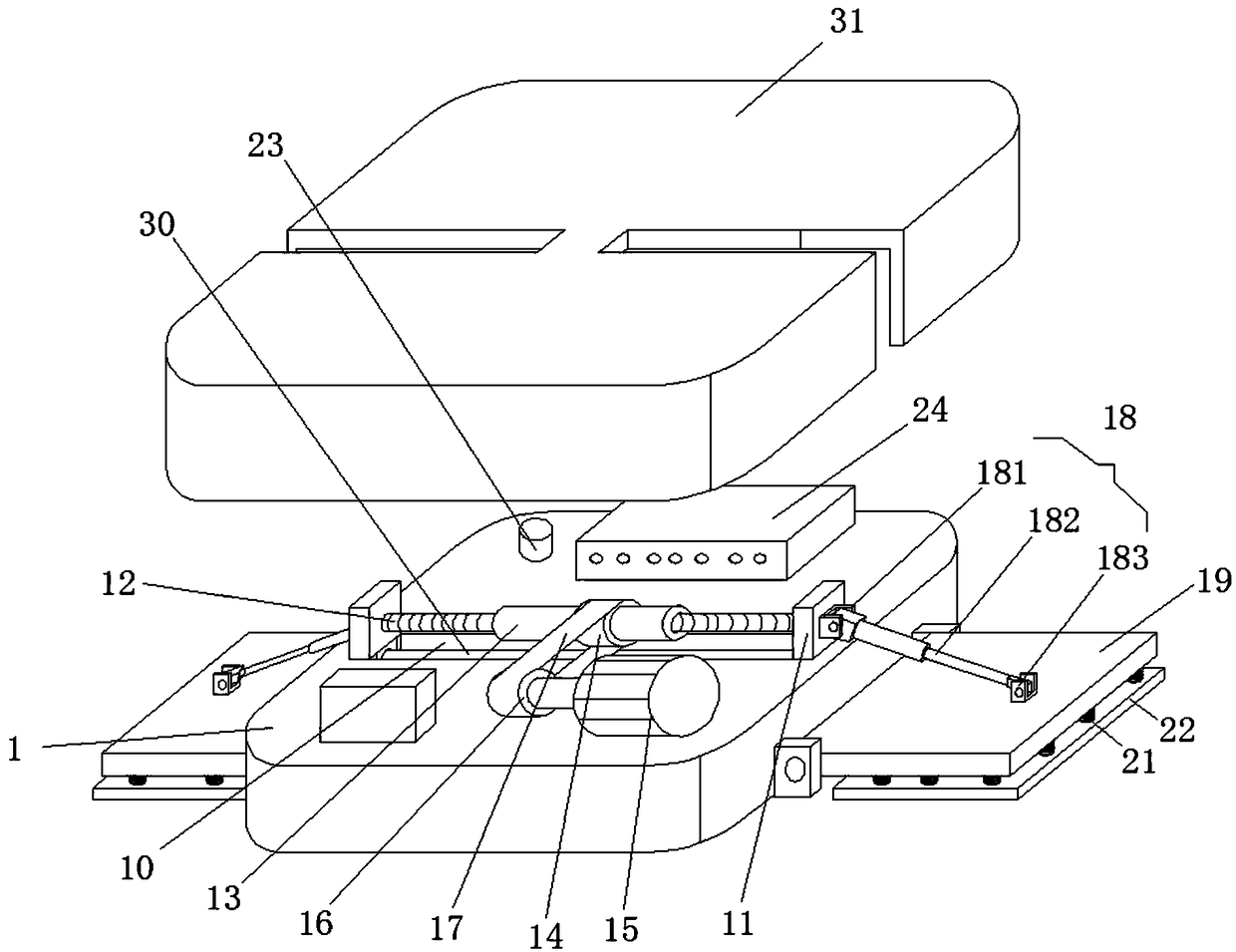
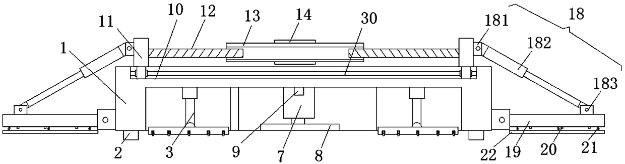
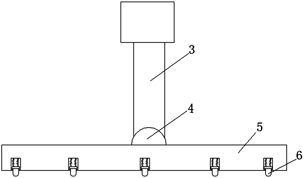
[0022] see Figure 1-4 , this embodiment provides an industrial robot suitable for use in machinery production workshops, including a housing 1, a drive wheel 2 is provided at the bottom of the housing 1, and a first push rod 3 is fixedly connected to the top of the inner wall of the housing 1, The bottom of the first push rod 3 is fixedly connected with the first hinged seat 4, the bottom of the first hinged seat 4 is hinged with the detection plate 5, the bottom of the detection plate 5 is provided with a movable column 6, and the top of the inner wall of the housing 1 is fixedly connected with the first hinged seat 4. Two push rods 7, the bottom of the second push rod 7 is movably connected with a marking brush plate 8, the front of the second push rod 7 is provided with a speed sensor 9, the top of the housing 1 is provided with a sliding groove 10, and the inner wall of the sliding groove 10 slides A sliding block 11 is connected, one side of the sliding block 11 is fixed...

Embodiment 2

[0025] see image 3 On the basis of Embodiment 1, a further improvement has been made: the bottom of the detection plate 5 is provided with evenly distributed installation grooves, the inner wall of the installation groove is movably connected with a second spring, and the second spring is fixedly connected with the movable column 6. By setting the first The second spring and the installation groove can make the positioning column 6 shrink into the inside of the installation groove during the movement of the robot, so as to prevent its protrusion from causing the robot to hang in the air. and the thread directions of the two screw mandrels 12 are opposite. When the servo motor 15 rotates, the belt pulley 16 will drive the belt 17 to move, and the belt 17 will drive the pulley 14 to rotate, so that the screw mandrel sleeve 13 will rotate. The threads of the two screw rods 12 are set in reverse, so that when the screw rod sleeve 13 rotates, the two screw rods 12 move relative to...

Embodiment 3

[0028] see image 3 On the basis of Embodiment 1, a further improvement is made: the adjustment device 18 includes a second hinged seat 181, the second hinged seat 181 is fixedly connected with the sliding block 11, and the end of the second hinged seat 181 away from the sliding block 11 is hinged with an air pressure Rod 182, the model of preferred air pressure rod 182 is JL-1015, and the side of air pressure rod 182 far away from the second hinge seat 181 is hinged with the third hinge seat 183, and the third hinge seat 183 is fixedly connected with support plate 19. When the inclination angle of the plate 22 is adjusted, the air pressure rod 182 can be stretched. When the air pressure rod 182 is stretched, the air pressure rod 182 can rotate around the second hinge seat 181, so that the air pressure rod 182 can pull or push the support plate 19 , so that the inclination angle thereof is changed, so that the inclination angle of the detection plate 22 can be changed.


PUM


Abstract

The invention discloses an industrial robot suitable for use in a machinery production workshop, and the robot comprises a housing. The bottom of the housing is provided with a driving wheel, and thetop of the inner wall of the housing is fixedly connected with a first push rod. The bottom of the first push rod is fixedly connected with a first hinge seat, and the bottom of the first hinge seat is hinged to a detection disc. The bottom of the detection disc is provided with a movable column, and the top of the inner wall of the housing is fixedly connected with a second push rod. The bottom of the second push rod is movably connected with a marking brush plate, and the front surface of the second push rod is provided with a speed sensor. The top of the housing is provided with a sliding groove, and the inner wall of the sliding groove is slidably connected a sliding block, wherein one side of the sliding block is fixedly connected with a screw. The industrial robot solves the problemsthat the detection efficiency is low, the detection effect is not good and no convenience can be brought to a user, which are caused by a condition that most of the conventional steel plate or steelmaterial flatness detection modes are modes of manual measurement via measuring tools.

Description

technical field [0001] The invention relates to the technical field of industrial robots, in particular to an industrial robot suitable for use in machinery production workshops. Background technique [0002] An industrial robot is a multi-joint manipulator or a multi-degree-of-freedom machine device for the industrial field. It can perform work automatically. It is a machine that realizes various functions by its own power and control capabilities. It can accept human commands or follow instructions Running pre-programmed programs, modern industrial robots can also act according to the principles and programs formulated by artificial intelligence technology. [0003] In the process of mechanical production, the processing of steel plate or block steel is the most commonly used material in the production workshop. After the preliminary processing of the newly processed steel plate or steel, it needs to be tested for its flatness. Most of the existing detection methods are ma...

Claims


Application Information

Patent Timeline
Patent Type & Authority Applications(China)
IPC IPC(8): G01B5/28B25J11/00
CPCB25J11/00G01B5/28
Inventor 陈律希
Owner 南京艾依曼环保科技有限公司
Why Eureka
Try Eureka