Fiber cutting device and working method thereof
An optical fiber and optical fiber frame technology, applied in the field of optical fiber cutting process and optical fiber rolling and cutting device, can solve the problems of uneven ends, inconvenient coating and shaping, etc., and achieve the effect of high-efficiency rolling and cutting, easy promotion, and convenient adjustment.
- Summary
- Abstract
- Description
- Claims
- Application Information
AI Technical Summary
Problems solved by technology
Method used
Image

Examples
Embodiment 1
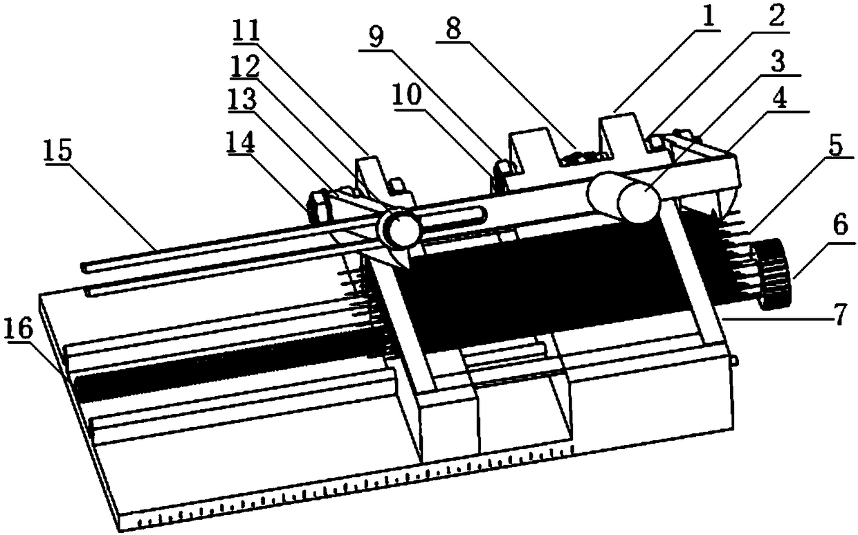
[0048] An optical fiber rolling and cutting device includes a base. Rolling knives are arranged on both sides of the base. The rolling knives are connected to the base through a rotating shaft.
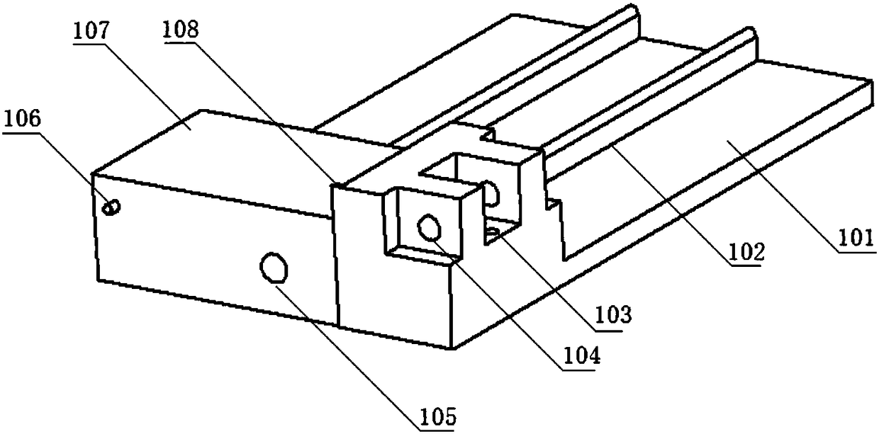
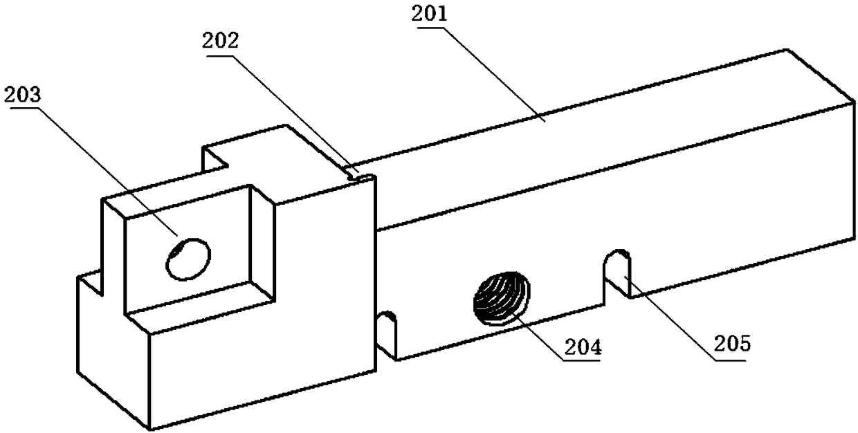
[0049] Among them: the base includes the base right 1 and the base left 11, the base right 1 is provided with a right-angle step, including the rolling and cutting table right 107 and the support table 101, the rolling and cutting table right is used to carry the right half of the optical fiber rack and the rolling and cutting of the optical fiber, The supporting platform 101 is provided with a guide rail 102, and the number of the guide rails is two. The lower half of the cross section of the guide rail is rectangular, and the upper half is semicircular; There is a guide rail groove 205, which is matched with the guide rail 102. Above the base left 11 is the left rolling and cutting table 201. The left rolling and cutting table is used to carry the left half of the optical fiber rack ...
Embodiment 2
[0053] An optical fiber rolling and cutting device, the structure of which is as described in Embodiment 1, the difference is that a limit pin 106 is provided on the side of the base, and a limit groove 402 is provided at the corresponding position of the rolling knife. When the rolling knife falls, the limit groove moves to the limit pin, because the existence of the limit pin prevents the rolling knife from continuing to move down.
Embodiment 3
[0055] An optical fiber rolling and cutting device, the structure of which is as described in Embodiment 1, the difference is that the optical fiber rolling and cutting device also includes a lead screw 16, which is located in the middle of the two guide rails in the horizontal direction, and the right base 1 is provided with a lead screw hole 105, the lead screw hole is used to accommodate the unthreaded end of the lead screw 16, the base left 11 is provided with a lead screw threaded hole 204, the lead screw 16 runs through the lead screw hole 105 and the lead screw threaded hole 204 is provided, and the lead screw 16 is provided at one end Nut A6. When the nut rotates, the lead screw rotates, and the left side of the base moves horizontally along the guide rail on the right side of the base through the threaded hole of the lead screw.
PUM
 Abstract
Description
Claims
Application Information
 - R&D Engineer
- R&D Manager
- IP Professional
- Industry Leading Data Capabilities
- Powerful AI technology
- Patent DNA Extraction
Browse by: Latest US Patents, China's latest patents, Technical Efficacy Thesaurus, Application Domain, Technology Topic.
© 2024 PatSnap. All rights reserved.Legal|Privacy policy|Modern Slavery Act Transparency Statement|Sitemap