
Display device

A technology for display devices and liquid crystal display panels, applied in nonlinear optics, instruments, optics, etc., can solve problems such as limited resolution of display systems, no intersection, and adjacent viewpoint interference.

Active Publication Date: 2018-12-11
BOE TECH GRP CO LTD +1
View PDF7 Cites 8 Cited by
  • Summary
  • Abstract
  • Description
  • Claims
  • Application Information

AI Technical Summary

Problems solved by technology

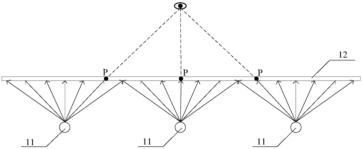
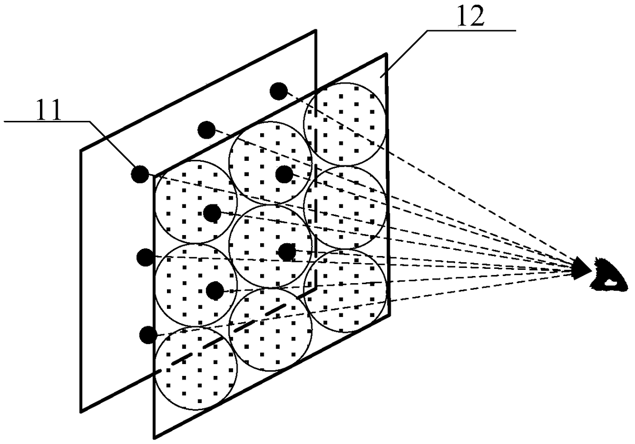
[0004] However, if figure 2 As shown, in the above display system structure, there can be no intersection between the light spots projected by two adjacent miniature light-emitting diodes 11 onto the liquid crystal panel 12, otherwise it will cause interference between adjacent viewpoints, thereby limiting the resolution of the display system

Method used


Image

  • Display device
  • Display device
  • Display device

Examples


Embodiment Construction

[0037] An embodiment of the present invention provides a display device for improving display resolution.

[0038] In order to make the purpose, technical solution and advantages of the present invention clearer, the present invention will be further described in detail below in conjunction with the accompanying drawings. Apparently, the described embodiments are only some of the embodiments of the present invention, rather than all of them. Based on the embodiments of the present invention, all other embodiments obtained by persons of ordinary skill in the art without making creative efforts belong to the protection scope of the present invention.

[0039] The display device provided by the specific embodiments of the present invention will be described in detail below with reference to the accompanying drawings.

[0040] In light field display applications, each point light source can be used as a light-emitting unit, and its emitted light is modulated by the liquid crystal ...


PUM


Abstract

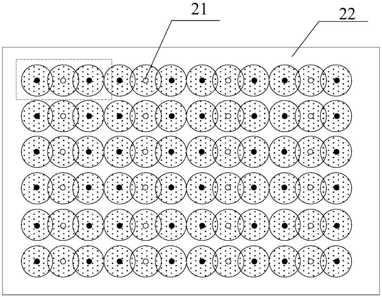
The invention discloses a display device which comprises multiple polarized-point light sources, a first polarizing plate and a second polarizing plate. A liquid crystal display panel is arranged at the set distance of the light emitting side of the polarized-point light sources, the first polarizing plate is located on the surface of the liquid crystal display panel facing one side of the polarized-point light sources, and the second polarizing plate is located on the surface of the liquid crystal display panel away from one side of the polarized-point light sources; polarized light emitted from two adjacent polarized-point light sources with the overlapping area of light spots projected onto the liquid crystal display panel is perpendicular to each other in the polarization direction; since the polarization direction of the first polarizing plate of the overlapping area of the light spots is only identical to the polarization direction of the polarized-point light source corresponding to the light spots in the overlapping area of the light spots, only the emitting light of one polarized-point light source can penetrate the overlapping area even if the overlapping area of the light spots exists, light interference in the overlapping area of two point light sources can be avoided, and more polarized-point light sources can be arranged at the display area of the display device to improve display resolution.

Description

technical field [0001] The present invention relates to the field of display technology, in particular to a display device. Background technique [0002] A traditional display panel is generally composed of a plurality of display pixels, forming a pixel array on the display surface, and the display images viewed by the viewer are almost the same no matter from which viewing angle. However, in the real world, when the viewer's position or viewing angle changes, the viewed image is different, so the display effect of the traditional display panel is less authentic. Therefore, the light field display technology that came into being can record and reconstruct the light emitted by each point element on the object in all directions. The light field display can not only truly reproduce the spatial characteristics of the three-dimensional scene, but also express the relationship between different objects The mutual occlusion relationship has become a research hotspot in recent year...

Claims


Application Information

Patent Timeline
IPC IPC(8): G02F1/1335G02F1/13357
CPCG02F1/133528G02F1/133603G02F1/133531G02F1/133548
Inventor 胡伟频张洪术姜明宵
Owner BOE TECH GRP CO LTD
Learn More