Aircraft with V-shaped tail wing and multi-rotor vertical take-off and landing layout

A vertical take-off and landing, multi-rotor technology, applied in the field of aircraft, can solve the problems of high flight resistance, difficult take-off and landing, weak wind resistance, etc., to achieve the effect of enhancing wind resistance, improving wind resistance, and small windward area

Pending Publication Date: 2020-08-14
CHINA AERODYNAMICS RES & DEV CENT
View PDF20 Cites 2 Cited by
  • Summary
  • Abstract
  • Description
  • Claims
  • Application Information

AI Technical Summary

Problems solved by technology

[0003] At present, the multi-rotor compound vertical take-off and landing aircraft has the disadvantages of large flight resistance, weak wind resistance, poor directional stability, etc. because the multi-wing tips are exposed like rotors and rely on multi-rotor anti-twist for heading control; The fuselage of the seated vertical take-off and landing aircraft is in an upright state in the take-off and landing mode, and becomes horizontal in the level flight mode, which has problems such as a high center of gravity, difficult take-off and landing, and more complicated control; while the tilting vertical take-off and landing aircraft The tilting mechanism and control system are relatively complex and technically difficult

Method used


Image

  • Aircraft with V-shaped tail wing and multi-rotor vertical take-off and landing layout
  • Aircraft with V-shaped tail wing and multi-rotor vertical take-off and landing layout
  • Aircraft with V-shaped tail wing and multi-rotor vertical take-off and landing layout

Examples


Embodiment 1

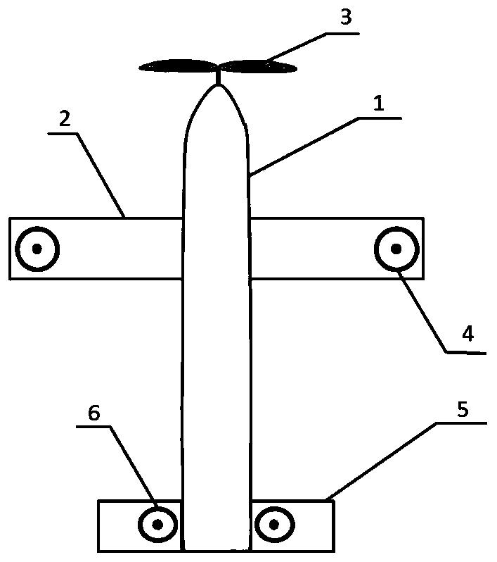
[0027] see figure 1 and figure 2 , an aircraft with a V-tail multi-rotor vertical take-off and landing layout, including a fuselage 1, a fixed wing 2, a V-shaped tail 5 and a power mechanism that provides the forward pulling force of the aircraft. The fixed wings 2 on both sides are symmetrically arranged near the tip The tip rotor 4, the rotation plane of the wing tip rotor 4 is located in the same plane as the fixed wing 2; the V-tail rotor 6 is symmetrically arranged in the two wing sections of the V-shaped tail 5, and the rotation planes of the two V-tail rotors 6 are in the same plane as The 5 wing sections of the V-shaped tail are located in the same plane.

[0028] In this embodiment, the vertical take-off and landing aircraft formed by the wingtip rotor 4 of the two fixed flanks 2 wingtips plus the V-tail rotor 6 of the V-tail 5 can significantly reduce the size of the aircraft by the arrangement of its hovering power or attitude assistance. resistance; in the case ...

Embodiment 2

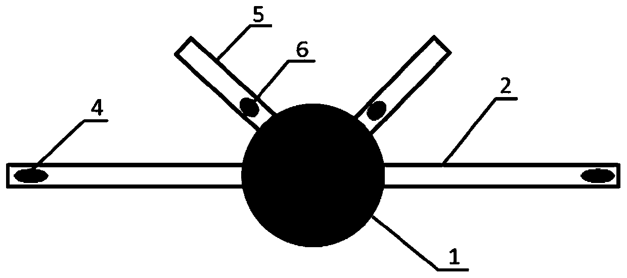
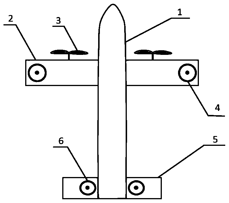
[0031] see image 3 , Figure 4 or Figure 5 , an aircraft with a V-tail multi-rotor vertical take-off and landing layout, including a fuselage 1, a fixed wing 2, a V-shaped tail 5 and a power mechanism that provides the forward pulling force of the aircraft. The fixed wings 2 on both sides are symmetrically arranged near the tip The tip rotor 4, the rotation plane of the wing tip rotor 4 is located in the same plane as the fixed wing 2; the V-tail rotor 6 is symmetrically arranged in the two wing sections of the V-shaped tail 5, and the rotation planes of the two V-tail rotors 6 are in the same plane as The 5 wing sections of the V-shaped tail are located in the same plane.

[0032] The aircraft adopts the vertical layout of the fixed side wings 2 wingtip rotors 4 and the V-tail rotor 6 of the V-shaped tail 5. The structure of the aircraft is simple and there is no blade interference problem of front-pull and rear-pull force, and it is compatible with a variety of Power la...

Embodiment 3

[0036] see Figure 6 , an aircraft with a V-tail multi-rotor vertical take-off and landing layout, including a fuselage 1, a fixed wing 2, a V-shaped tail 5 and a power mechanism that provides the forward pulling force of the aircraft. The fixed wings 2 on both sides are symmetrically arranged near the tip The tip rotor 4, the rotation plane of the wing tip rotor 4 is located in the same plane as the fixed wing 2; the V-tail rotor 6 is symmetrically arranged in the two wing sections of the V-shaped tail 5, and the rotation planes of the two V-tail rotors 6 are in the same plane as The 5 wing sections of the V-shaped tail are located in the same plane.

[0037] In the present embodiment, the two tip rotors 4 are two tilting rotors, and the two tilting rotors are respectively symmetrically arranged on the outer positions of the tips of the two fixed side wings 2 to form a tilting rotor aircraft, and the tilting rotor aircraft It is a set of rotor tilting system components that ...


PUM


Abstract

The invention relates to the technical field of aircrafts and discloses an aircraft with V-shaped tail wing and multi-rotor vertical take-off and landing layout. The aircraft comprises an aircraft body, fixed side wings, a V-shaped tail wing and a power mechanism for providing advancing tension for the aircraft. Wingtip rotor wings are symmetrically arranged at positions, close to a tip end, of the fixed side wings on the two sides, and rotating planes of the wingtip rotor wings and the side wings are located in the same plane; and V-shaped tail rotors are symmetrically arranged in the two wing sections of the V-shaped tail wing, and the rotating planes of the two V-shaped tail rotors and the wing sections of the V-shaped tail wing are located in the same plane. A layout form that the fourrotors are embedded into the wing tips of the wings on the two sides and the V-shaped tail wing is adopted, and the appearance layout of the aircraft can improve wind resistance of the multi-rotor aircraft, reduce resistance and improve a flight speed on the premise that structural strength of the aircraft body is ensured to be high and power is sufficient.

Description

technical field [0001] The invention relates to the technical field of aircraft, in particular to an aircraft with a V-shaped tail multi-rotor vertical take-off and landing layout. Background technique [0002] Vertical take-off and landing fixed-wing aircraft is a type of aviation fixed-wing aircraft that can take off and land vertically in a simple and narrow environment. It has the characteristics of simple take-off and landing, long flight time, and long range. The more common vertical take-off and landing drones mainly include multi-rotor compound vertical take-off and landing aircraft, tail-sit vertical take-off and landing aircraft and tilting vertical take-off and landing aircraft. [0003] At present, the multi-rotor compound vertical take-off and landing aircraft has the disadvantages of large flight resistance, weak wind resistance, poor directional stability, etc. because the multi-wing tips are exposed like rotors and rely on multi-rotor anti-twist for heading c...

Claims


Application Information

Patent Timeline
Patent Type & Authority Applications(China)
IPC IPC(8): B64C29/00B64D27/20B64C27/26
CPCB64C29/00B64D27/20B64C27/26
Inventor 杨小川刘刚付志毛仲君汪华松
Owner CHINA AERODYNAMICS RES & DEV CENT
Why Eureka
Try Eureka