
An IC chip burner

A burner and chip technology, applied in semiconductor/solid-state device manufacturing, conveyor objects, electrical components, etc., can solve problems affecting the efficiency of loading and unloading processing, unreasonable loading and unloading structure, simple structure, etc.

Inactive Publication Date: 2018-12-11
吴美珍
View PDF0 Cites 3 Cited by
  • Summary
  • Abstract
  • Description
  • Claims
  • Application Information

AI Technical Summary

Problems solved by technology

Most of the existing IC chip programmers directly deliver IC chips to the programming mechanism through the manipulator, and the structure is simple, which is not conducive to the expansion of other functions in the later stage
In addition, the IC chip needs to be coded before the IC chip is programmed. In the production of the existing IC chip, the IC chip programming and the code spraying operation are operated separately, and the existing multi-station IC chip programmer generally exists The problem is that the loading and unloading structure is unreasonable, which affects the efficiency of loading and unloading processing

Method used


Image

  • An IC chip burner
  • An IC chip burner
  • An IC chip burner

Examples


Embodiment Construction

[0035] Combine below Figure 1-Figure 18 The present invention is further described.

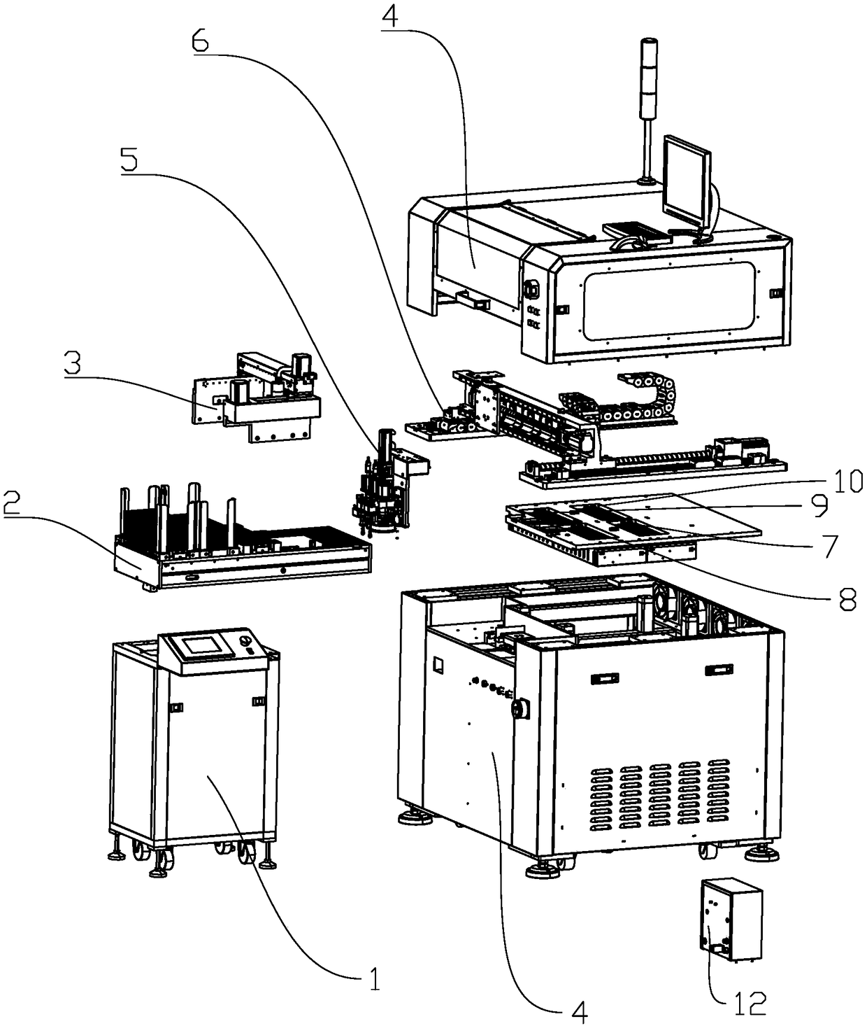
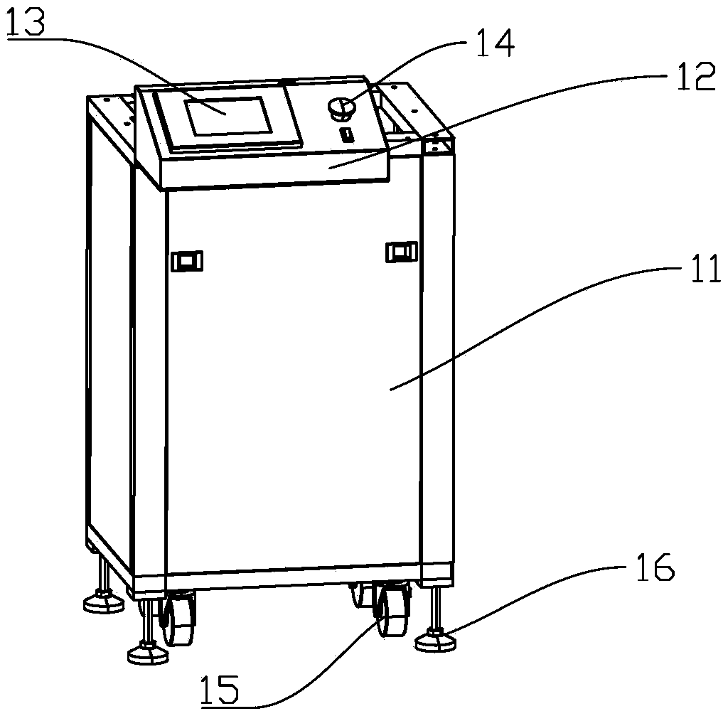
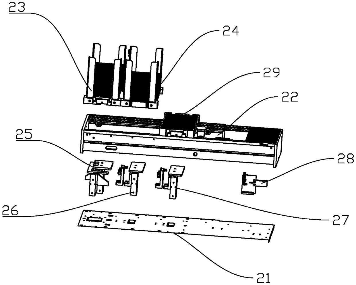
[0036] Such as Figure 1-Figure 18 A kind of IC chip burner shown, comprises feeding frame assembly 1, feeding mechanism 2, code spraying mechanism 3, burning frame assembly 4, manipulator mechanism, burning mechanism and air pressure regulating mechanism 12; The mechanism 2 and the coding mechanism 3 are installed on the loading frame assembly 1 , and the manipulator mechanism, the burning mechanism and the air pressure regulating mechanism 12 are installed on the burning frame assembly 4 .

[0037] Feeding mechanism 2 is used for IC chip loading, IC chip conveying and IC chip unloading; Coding mechanism 3 is located in the middle position of the upper part of feeding mechanism 2, and coding mechanism 3 is used for the IC chip on the feeding mechanism 2 Carry out coding processing; the manipulator mechanism is used for the handling of IC chips between the feeding mechanism 2 and the burni...


PUM


Abstract

The invention relates to the field of chip production and manufacture. An IC chip burner comprises a feeding rack assembly and a feeding mechanism thereon. The feeding mechanism comprises a fixed baseplate, a drive belt device, a first stacking device and a first lifting device. The advantages of the IC chip burner are that material is fed in an orderly manner from material plates holding IC chips, the processing efficiency is high, and other functions are convenient to expand.

Description

technical field [0001] The invention relates to the field of chip production and manufacturing, in particular to equipment for burning IC chips. Background technique [0002] With the development of electronic technology, the demand for chips continues to increase. In order to improve the efficiency of production, IC chip programmers have been widely used. Most of the existing IC chip programmers directly deliver IC chips to the programming mechanism through the manipulator, and the structure is simple, which is not conducive to the expansion of other functions in the later stage. In addition, the IC chip needs to be coded before the IC chip is programmed. In the production of the existing IC chip, the IC chip programming and the code spraying operation are operated separately, and the existing multi-station IC chip programmer generally exists The problem is that the loading and unloading structure is unreasonable, which affects the efficiency of loading and unloading proce...

Claims


Application Information

Patent Timeline
Patent Type & Authority Applications(China)
IPC IPC(8): H01L21/67H01L21/677
CPCH01L21/67011H01L21/677
Inventor 吴美珍
Owner 吴美珍
Learn More