
A commutation switch device and a dispatching application system adopting the commutation switch device

A technology of commutation switch and balance degree, which is applied in the direction of reducing the asymmetry of the multi-phase network, eliminating/reducing the asymmetry of the multi-phase network, etc., and can solve the unbalanced adjustment, the commutation switch module cannot receive the commutation command, and the application The system is not effective and other problems

Pending Publication Date: 2018-12-11
浙江百固电气科技股份有限公司
View PDF0 Cites 1 Cited by
  • Summary
  • Abstract
  • Description
  • Claims
  • Application Information

AI Technical Summary

Problems solved by technology

This scheme has the following defects: 1. When the main control commutator is abnormal, the lower commutation switch module will not receive the commutation command or lock the commutation function, and the entire application system will not be able to effectively and timely unbalance adjustment ; 2. Since the main control commutator needs to communicate with multiple commutation switch modules, that is, the one-to-many communication mode, the reliability of the main control commutator becomes the only core equipment for the trouble-free operation of the whole system, and the system has no faults. Redundancy, low reliability

Method used


Image

  • A commutation switch device and a dispatching application system adopting the commutation switch device
  • A commutation switch device and a dispatching application system adopting the commutation switch device
  • A commutation switch device and a dispatching application system adopting the commutation switch device

Examples


Embodiment Construction

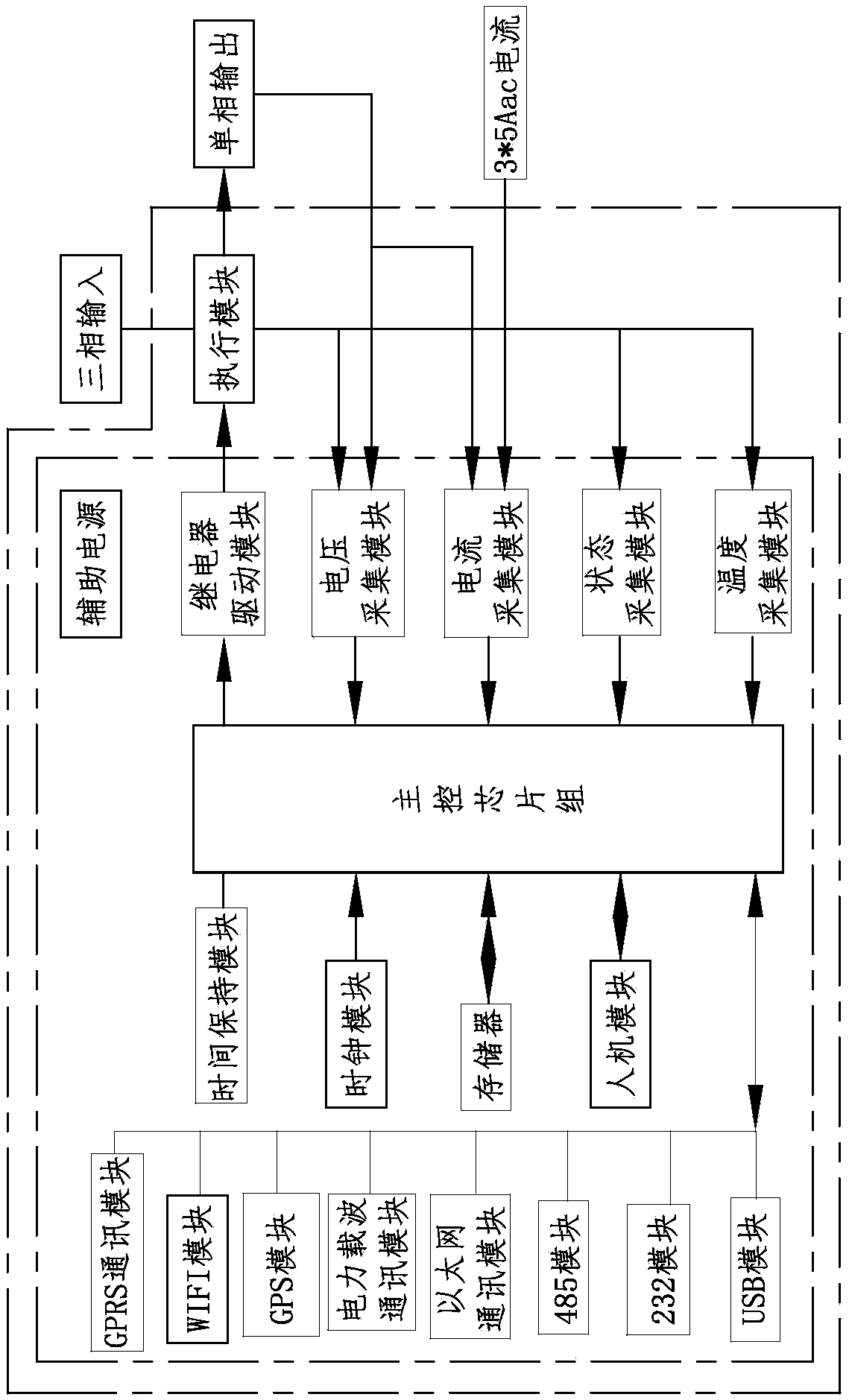
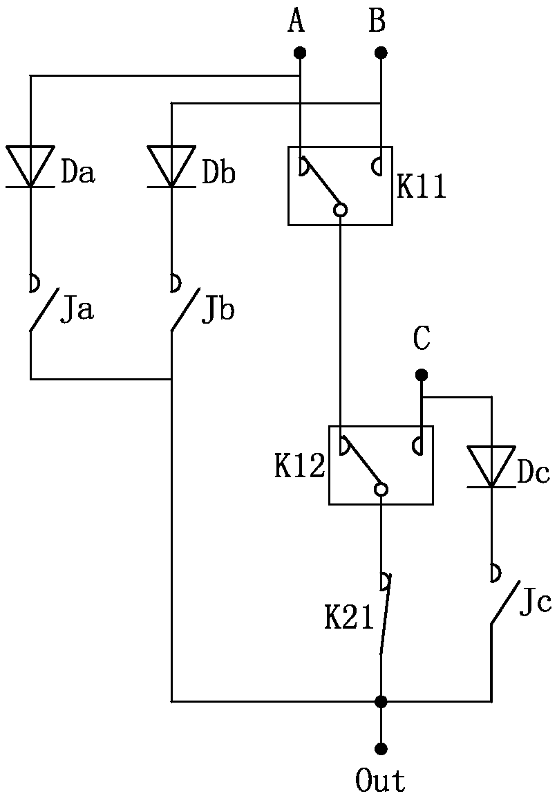
[0026] like Figure 1~3 As shown, a commutation switch device, including

[0027] Auxiliary power supply, used to provide power supply for the following units;

[0028] Executing module, used for executing the switch combination output in the main circuit of the reversing switch device;

[0029] The relay driving module is used to drive the breaking or closing of the switch in the main circuit;

[0030] The voltage acquisition module is used to acquire the three-phase power supply voltage on the output side of the power transformer;

[0031] The current collection module is used to collect the three-phase total current and leakage current on the output side of the power transformer, and the input current of each phase of the branch where the commutation switch device is located;

[0032] A state acquisition module is used to detect the state of the switch in the main circuit of the commutation switch device;

[0033] And the main control chipset. According to the voltage a...


PUM


Abstract

The invention relates to a commutating switch device. The device includes an auxiliary power, an execution module, a relay drive module, a voltage acquisition module, a current acquisition module, a state acquisition module and a main control chip set. According to voltage acquisition module and current acquisition module, main control chip set calculates power parameter values of each branch circuit under each feeder unit, and stores them in memory. When leakage current value exceeds leakage current standard value, main control chip set stops commutation. When the power parameter value otherthan the leakage current value is in the unbalanced adjustable range, the master control chip set outputs control commands to the relay driving module according to the commutation control sequence according to the state acquisition module. The commutation switch device has independent acquisition and commutation. In the structural scheme of unbalanced regulation of power line, the participation ofcommutation master controller is not required, the wiring is simple, and the maintenance is convenient. The commutation master controller can avoid the deterioration of the operation condition of power line caused by the failure of the commutation master controller when managing multiple commutation switch devices.

Description

technical field [0001] The invention relates to a phase change switch device, and also relates to a dispatching application system corresponding to the phase change switch device. Background technique [0002] In the power supply system, a three-phase power transformer is usually used for power supply, and the load side of the three-phase power transformer can have a feeder unit, and each feeder unit can distribute multiple three-phase electrical equipment and / or single-phase loads scatteredly. Ideally, the three-phase load on the electricity side of the power transformer is balanced, the zero line current is zero, and the energy loss of the transformer and the power supply line is small. However, the actual power consumption environment is complex, and it is difficult to achieve three-phase balance. At this time, the single-phase load needs to be switched from a heavy-load phase to a light-load phase to achieve a state close to three-phase balance. [0003] Generally, as a...

Claims


Application Information

Patent Timeline
IPC IPC(8): H02J3/26
CPCH02J3/26Y02E40/50
Inventor 蒋钱良黄颖博
Owner 浙江百固电气科技股份有限公司
Learn More