
Vertical rotary cone ball mill

A kind of technology of rotating cone ball and mill, applied in the field of mining machinery, can solve the problems of easy damage and low processing efficiency, and achieve the effect of reducing the number of maintenance, simplifying the process, and increasing the effective working time.

Active Publication Date: 2018-12-14
CHANGSHA UNIVERSITY
View PDF11 Cites 2 Cited by
  • Summary
  • Abstract
  • Description
  • Claims
  • Application Information

AI Technical Summary

Problems solved by technology

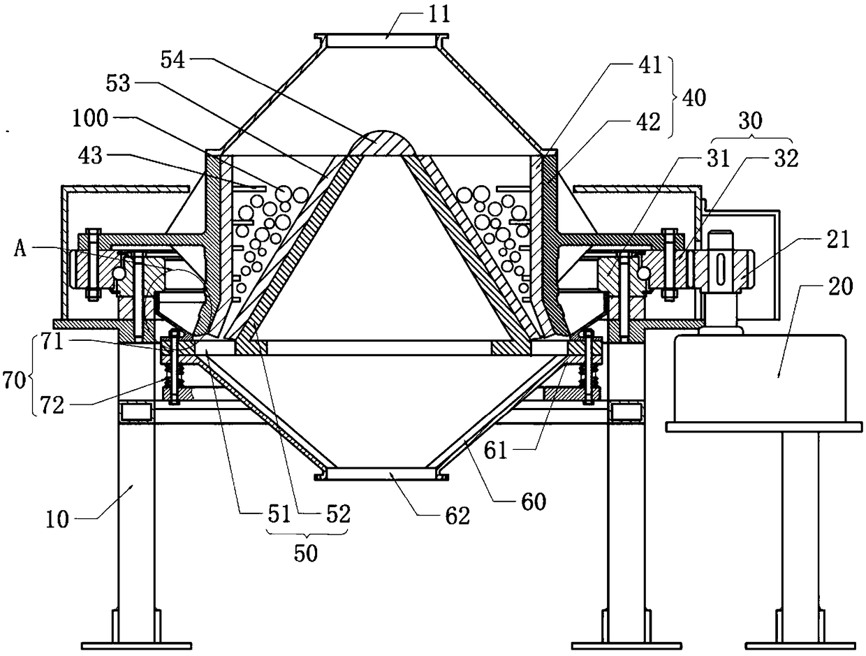
[0005] The main purpose of the present invention is to provide a vertical spiral cone ball mill, aiming to solve the problem of low processing efficiency and easy damage of existing ball mill crushing equipment

Method used


Image

  • Vertical rotary cone ball mill
  • Vertical rotary cone ball mill

Examples


Embodiment Construction

[0023] The technical solutions in this embodiment will be clearly and completely described below in conjunction with the accompanying drawings in this embodiment. Obviously, the described embodiments are only part of the embodiments of the present invention, not all of them. Based on the embodiments of the present invention, all other embodiments obtained by persons of ordinary skill in the art without creative efforts fall within the protection scope of the present invention.

[0024] It should be noted that all directional indications (such as up, down, left, right, front, back...) in this embodiment are only used to explain the relative relationship between the various components in a certain posture (as shown in the figure). When the positional relationship, movement conditions, etc., if the specific posture changes, the directional indication will also change accordingly.

[0025] In addition, in the present invention, descriptions such as "first", "second" and so on are ...


PUM


Abstract

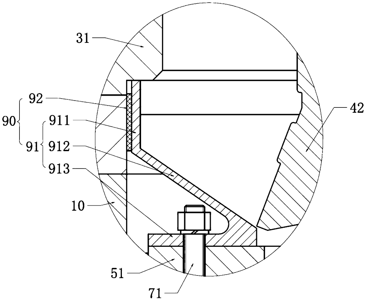
The invention discloses a vertical rotary cone ball mill. The vertical rotary cone ball mill comprises a mill body, a driving mechanism as well as slewing bearings, a movable cone device, a fixed conedevice, buffer devices and a plurality of grinding balls which are all arranged on the mill body, wherein the driving mechanism can drive the movable cone device to rotate around the axis of the fixed cone device through the slewing bearing, the fixed cone device is arranged on the mill body through the buffer device, and the grinding balls are arranged between the movable cone device and the fixed cone device for grinding materials together. Materials can be fully ground by cooperation of the slewing bearing, the grinding balls and the buffer device, effective working hours of the vertical rotary cone ball mill are increased, maintenance frequency can be reduced, and accordingly, working efficiency and grinding effect of the vertical rotary cone ball mill can be greatly improved.

Description

technical field [0001] The invention relates to the field of mining machinery, in particular to a vertical cone ball mill. Background technique [0002] At present, the equipment used for mixing and grinding mine materials is mainly agitator and ball mill. Most of the existing agitating ball mills are vertical spiral agitating ball mills. Stirring shaft, the material circulates between the stirring ball mill and the stirring tank. The dry stirring ball mill currently used only fixes the upper end of the main shaft, which is easy to shake when the main shaft is running at high speed, shortening the life of the main machine, and the grinding balls are circulated and discharged according to the fixed raceway. Ball, low production efficiency. The existing ball mill is the key equipment for crushing after the material is crushed, and it can carry out dry or wet grinding to various ores and other grindable materials. Most of the current ball milling and crushing equipment simply...

Claims


Application Information

Patent Timeline
Patent Type & Authority Applications(China)
IPC IPC(8): B02C2/04B02C17/10
CPCB02C2/04B02C17/10
Inventor 谈峰唐蒲华陈蕾
Owner CHANGSHA UNIVERSITY
Learn More