
Municipal drainage three-way tube casting body cutting equipment

A cutting equipment and municipal drainage technology, which is applied in the field of municipal drainage tee pipe casting body cutting equipment, can solve the problems of automatic transmission of tee flange pipes, inability to fix tee flange pipes, poor grinding effect of tee flange pipes, etc. question

Active Publication Date: 2018-12-14
平邑现代中药产业园有限公司
View PDF5 Cites 10 Cited by
  • Summary
  • Abstract
  • Description
  • Claims
  • Application Information

AI Technical Summary

Problems solved by technology

[0004] In order to solve the above problems, the present invention provides a municipal drainage tee pipe casting body cutting equipment, which can solve the problem of high manual labor intensity and the inability to cut the casting protrusions of the existing tee flange pipes. Automatic transmission, unable to fix the tee flange pipe according to its structure, the tee flange pipe is not fixed firmly, the tee flange pipe needs to be cut manually, and the tee flange pipe after cutting has poor grinding effect, etc. ; It can realize the fixed transmission of the cast tee flange pipe and the cutting and grinding function of the casting protrusion of the tee flange pipe. It has the functions of low labor intensity, automatic transmission of the tee flange pipe, The structure of the flange pipe fixes it, the three-way flange pipe is firmly fixed, the mechanized cutting of the three-way flange pipe is performed, and the cutting effect of the three-way flange pipe is good, etc.

Method used


Image

  • Municipal drainage three-way tube casting body cutting equipment
  • Municipal drainage three-way tube casting body cutting equipment
  • Municipal drainage three-way tube casting body cutting equipment

Examples


Embodiment Construction

[0031] In order to make the technical means, creative features, goals and effects achieved by the present invention easy to understand, the present invention will be further described below in conjunction with specific illustrations. It should be noted that, in the case of no conflict, the embodiments in the present application and the features in the embodiments can be combined with each other.

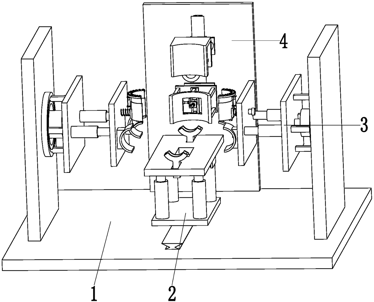
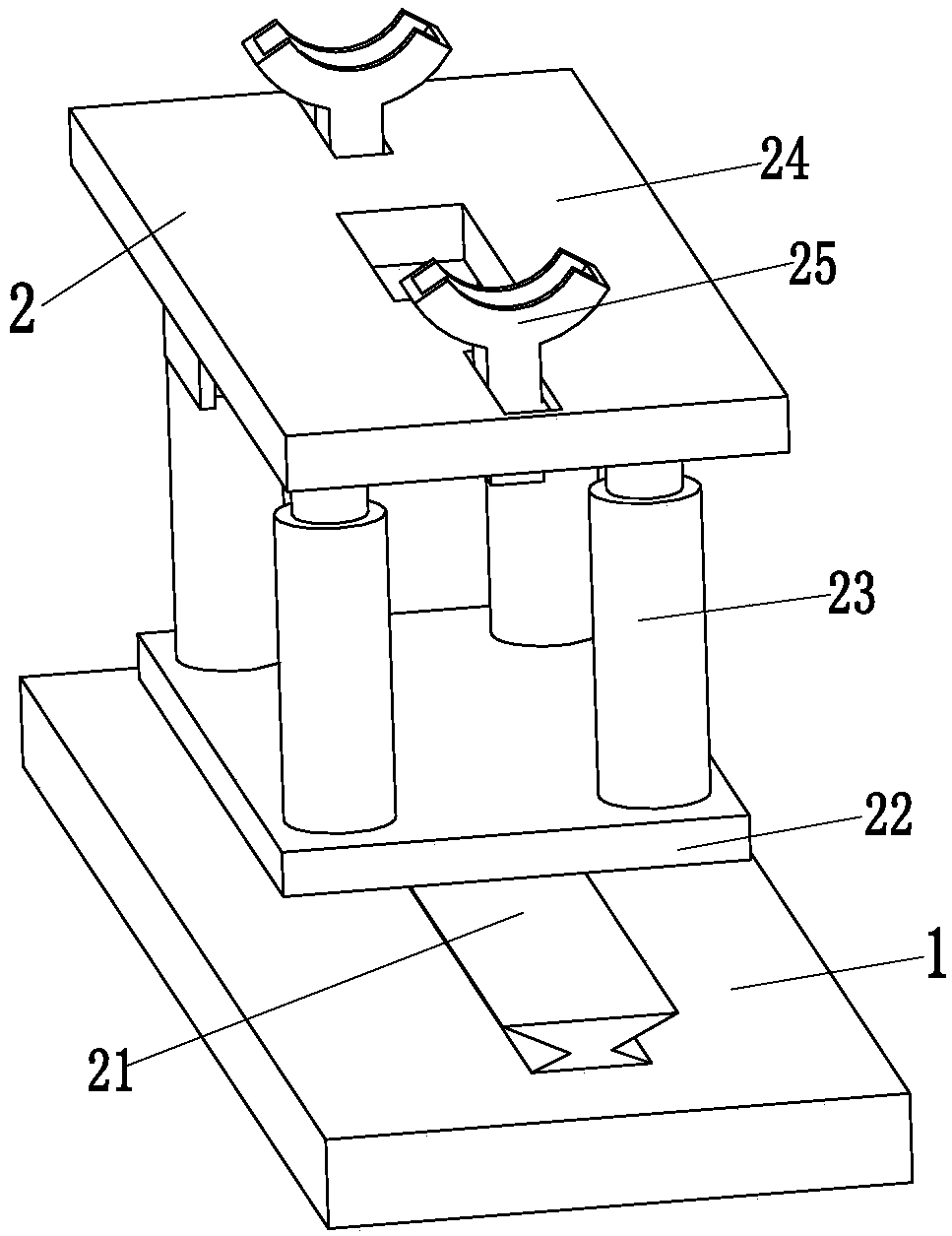
[0032] like Figure 1 to Figure 10 As shown, a municipal drainage tee pipe casting body cutting equipment includes a support base plate 1, a transmission device 2, a fixing device 3 and a cutting device 4, and a transmission device 2 is installed on the upper end surface of the middle part of the support base plate 1 to transmit The left and right sides of device 2 are all distributed with a fixture 3, and fixture 3 is installed on the outer end top of support base plate 1, and cutting device 4 is positioned at the rear side of conveying device 2, and cutting device 4 is installed on...


PUM


Abstract

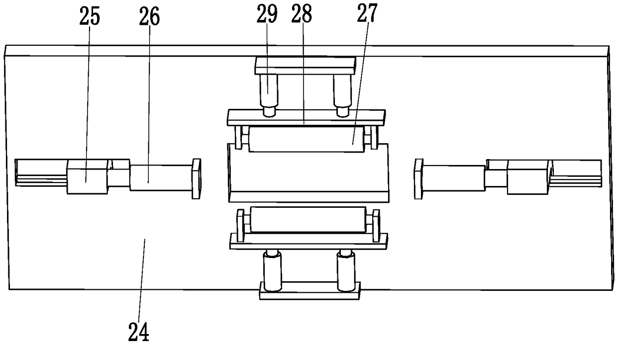
The invention relates to municipal drainage three-way tube casting body cutting equipment. The municipal drainage three-way tube casting body cutting equipment comprises a supporting bottom plate, a conveying device, fixing devices and a cutting device. The conveying device is mounted on the upper end surface of the middle of the supporting bottom plate. The two fixing devices are distributed on the left and right sides of the conveying device correspondingly and mounted at the outer end top of the supporting bottom plate. The cutting device is located on the rear side of the conveying deviceand mounted on the supporting bottom plate. The conveying device comprises a conveying electric sliding block, a conveying bottom plate, a conveying push rod, a conveying support plate, a storing frame, a storing push rod, a position correcting idler wheel, an idler wheel bracket and a position correcting push rod. According to the municipal drainage three-way tube casting body cutting equipment,the difficult problems that when an existing three-way flange tube is subjected to casted bulge cutting, the three-way flange tube cannot be automatically conveyed, the structure of the three-way flange tube cannot be fixed, the three-way flange tube is infirm in fixing and needs to be cut manually, and the cut three-way flange tube is poor in polishing effect can be solved.

Description

technical field [0001] The invention relates to the field of municipal material processing, in particular to a cutting device for a municipal drainage tee pipe casting body. Background technique [0002] Nowadays, with the development of society, municipal renovations are becoming more and more frequent, and the amount of tee flange pipes used in municipal pipeline replacement is also increasing year by year. The production of tee flange pipes is generally completed by casting, and the tee method after casting The blue pipe needs to cut and polish its casting protrusions. [0003] Nowadays, some small foundry companies generally use semi-automatic methods to fix and polish the tee flange pipe. First, the tee flange pipe is fixed manually with a clamp, and the casting protrusion is manually cut by a cutting machine. Finally, use the grinding wheel to polish the three-way flange pipe to make it smooth. The problems of this working method are as follows. The temperature of the...

Claims


Application Information

Patent Timeline
Patent Type & Authority Applications(China)
IPC IPC(8): B22D31/00
CPCB22D31/00
Inventor 不公告发明人
Owner 平邑现代中药产业园有限公司
Learn More