Laser welding method

A technology of laser welding and laser welding head, which is applied in the direction of laser welding equipment, welding equipment, metal processing equipment, etc., and can solve problems such as troublesome operation and damage to health

Inactive Publication Date: 2018-12-14
WENZHOU FIBER LASER
View PDF7 Cites 0 Cited by
  • Summary
  • Abstract
  • Description
  • Claims
  • Application Information

AI Technical Summary

Problems solved by technology

[0002] In the laser welding process of the existing machine tool, when clamping the workpiece, the operator needs to lean over and enter the processing chamber to ensure accurate clamping, but the operation is cumbersome, and when changing parts, the previous welding process will Harmful gas is produced, and workers enter the processing warehouse and come into contact with the gas, which will damage their health

Method used


Image

  • Laser welding method
  • Laser welding method
  • Laser welding method

Examples


specific Embodiment approach

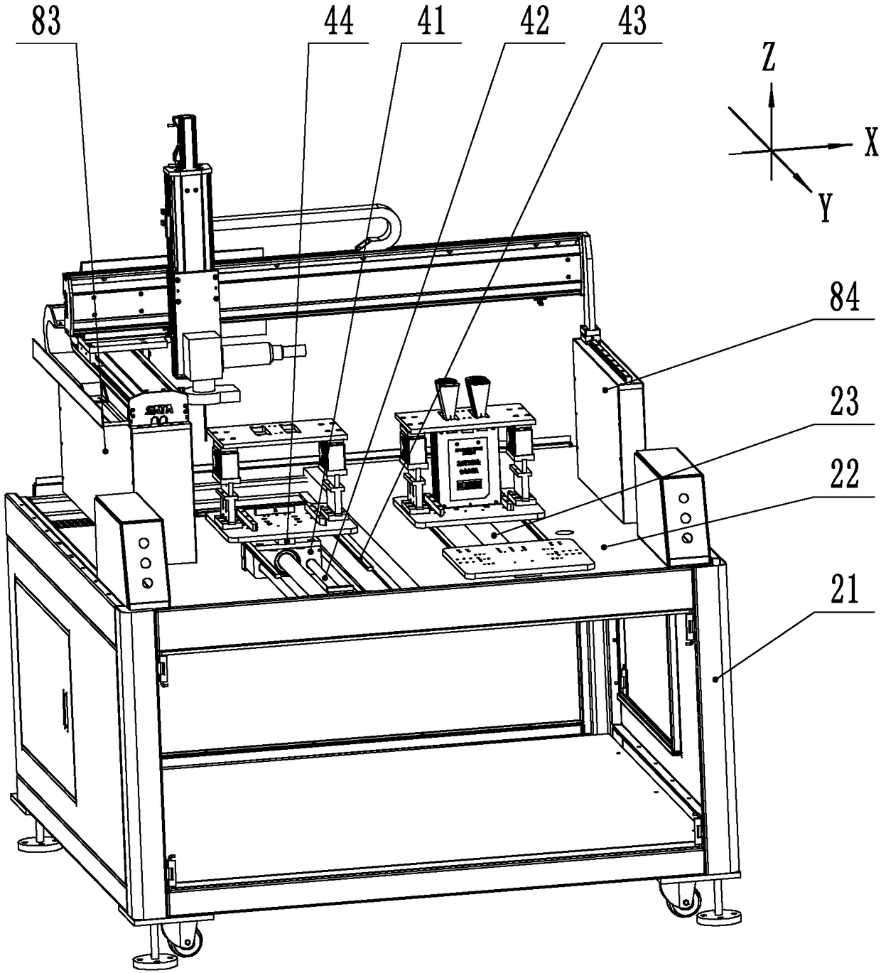
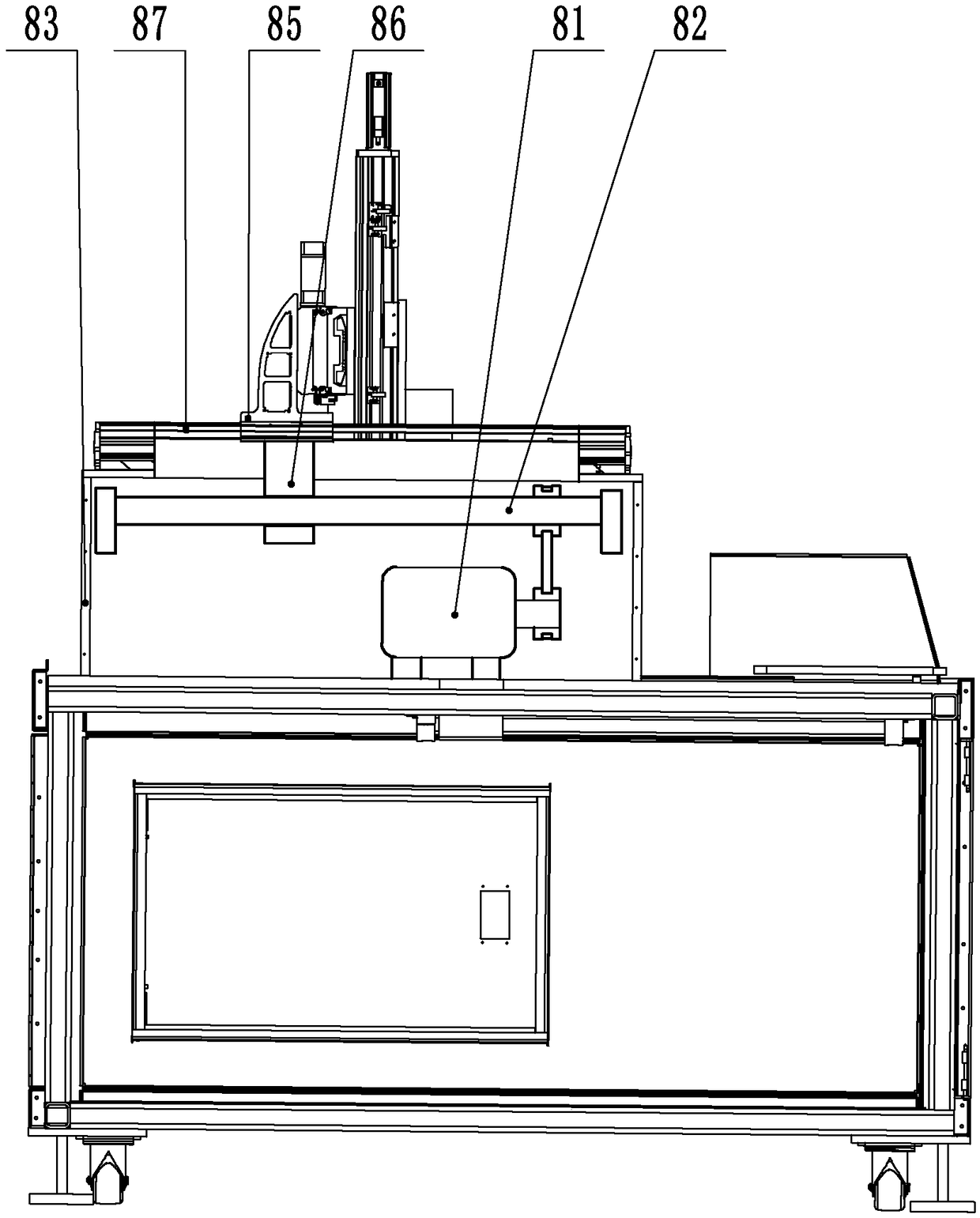
[0036] As an improved specific embodiment, the control mechanism 3 includes an X moving device, a Y moving device and a Z moving device, and the Y moving device includes a Y motor 81, a Y screw 82, a Y chassis 83 and a Y support 84 arranged along the Y direction. , the Y chassis 83 and the Y support 84 are arranged on opposite sides of the workbench 2 parallel to each other and extend along the direction of the operating station 5 and the processing zero position 6, and the top of the Y chassis 83 and the top of the Y support 84 are set There is a Y guide rail 87, a Y motor 81 is installed in the Y case 83, a Y screw 82 is rotated and installed in the Y case 83 and connected with the Y motor 81, a Y guide sleeve 85 is arranged on the X moving device, and the Y guide sleeve 85 and the Y guide rail 87 engagement, the bottom of the Y guide sleeve 85 is fixed with a Y screw sleeve 86, the Y screw sleeve 86 is engaged with the Y screw rod 82, and the X moving device includes an X mo...


PUM


Abstract

The invention discloses a laser welding method. The laser welding method comprises the steps that firstly, a clamp is arranged on a workbench; secondly, a moving device moves the clamp to an operationstation from a machining zero position; thirdly, an operator installs a component to the clamp; fourthly, the clamp and the component are moved to the machining zero position from the operation station; and fifthly, a control mechanism controls a laser welding head to move, a welding line is formed on the component, and the component is welded. Through the above steps, the clamp is moved to the operation station, the operation distance of the operator is shortened, operation is convenient, and after operation is convenient, control over the component from a worker is improved, and operation accuracy is improved. The clamp and the component are sent to the position near the operation station, the body of the worker can conduct operation without entering a work bin, and hurt to the worker from harmful gases is reduced.

Description

technical field [0001] The invention relates to a processing technology, more specifically to a laser welding method. Background technique [0002] In the laser welding process of the existing machine tool, when clamping the workpiece, the operator needs to lean over and enter the processing chamber to ensure accurate clamping, but the operation is cumbersome, and when changing parts, the previous welding process will Harmful gas is produced, and workers enter the processing warehouse and come into contact with the gas, which will damage their health. Contents of the invention [0003] In view of the deficiencies in the prior art, the object of the present invention is to provide a laser welding method, so that workers can clamp parts without entering the processing chamber. [0004] In order to achieve the above object, the present invention provides the following technical solutions: a laser welding method, comprising [0005] Step 1: Install the fixture on the workben...

Claims


Application Information

Patent Timeline
Patent Type & Authority Applications(China)
IPC IPC(8): B23K26/21B23K26/08B23K26/70
CPCB23K26/0884B23K26/21B23K26/702
Inventor 程国军余勤跃扈金富
Owner WENZHOU FIBER LASER
Why Eureka
Try Eureka