Special-shaped part machining clamping mechanism

A clamping mechanism and a technology for special-shaped parts, which are used in metal processing machinery parts, metal processing equipment, clamping and other directions, can solve the problems of affecting processing accuracy, difficult to clamp and firm special-shaped parts, etc., and achieve good clamping and fixing effect.

Active Publication Date: 2018-12-14
XIANGYANG YUQING TRANSMISSION TECH
View PDF7 Cites 2 Cited by
  • Summary
  • Abstract
  • Description
  • Claims
  • Application Information

AI Technical Summary

Problems solved by technology

[0005] The purpose of the present invention is to provide a clamping mechanism for processing special-shaped parts, which can solve the problem that in the field of mechan

Method used


Image

  • Special-shaped part machining clamping mechanism

Examples


Embodiment Construction

[0023] The technical solutions of the present invention will be clearly and completely described below in conjunction with specific embodiments. Apparently, the described embodiments are only some of the embodiments of the present invention, not all of them. Based on the embodiments of the present invention, all other embodiments obtained by persons of ordinary skill in the art without creative efforts fall within the protection scope of the present invention.

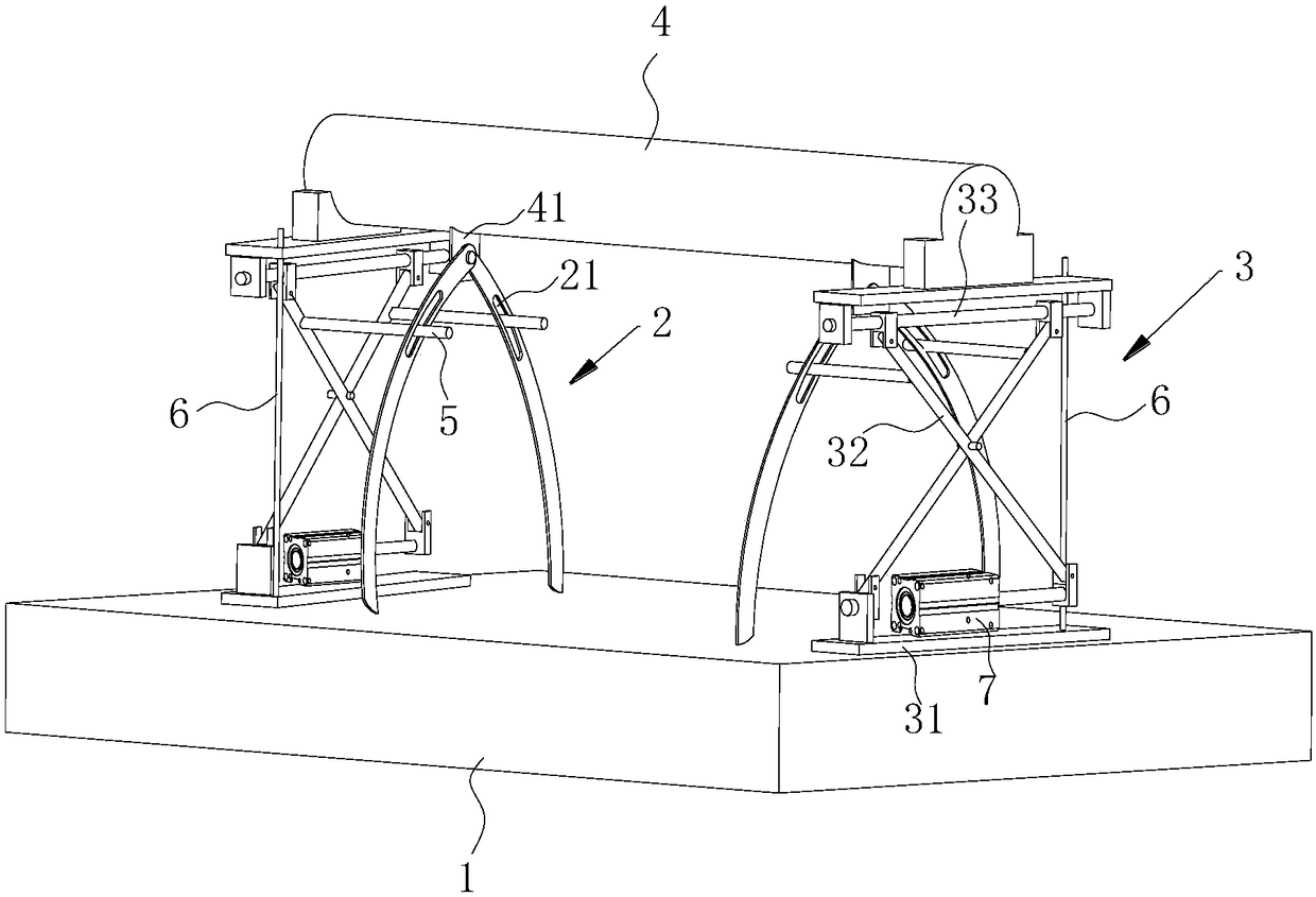
[0024] A clamping mechanism for special-shaped parts processing, refer to figure 1 , including a horizontally placed workbench 1 and a clamping assembly installed above the workbench 1 , the clamping assembly includes a crossbar 4 and a V-shaped plate 2 connected to the crossbar 4 and located below the crossbar 4 . The two ends of the crossbar 4 are respectively supported above the workbench 1 by the support assembly 3, and the crossbar 4 and the support assembly 3 are integrated; When processing the workpiece, the w...


PUM


Abstract

The invention relates to the technical field of machining, in particular to a special-shaped part machining clamping mechanism. The problem that in the field of machining, when a special-shaped part without a regular shape is machined, the special-shaped part cannot be firmly clamped easily, and the machining precision is affected is solved. According to the technical scheme, the special-shaped part machining clamping mechanism is characterized in that the special-shaped part machining clamping mechanism comprises a workbench; a V-shaped plate with an opening facing upwards and a supporting assembly for supporting the V-shaped plate are movably arranged on the upper portion of the workbench; and the height of the supporting assembly is adjustable. By adopting the technical scheme, when a workpiece is machined, the workpiece can be clamped in a clamping cavity between the V-shaped plate and the end surface of the workbench, and then the workpiece can be machined through hole boring or other equipment. Compared with common clamps, the workpiece can be firmly clamped in the clamping cavity through the V-shaped plate, especially the special-shaped part without a regular shape, and thesituation that the workpiece rotates in the clamping cavity, and the machineing accuracy of the workpiece is affected can be well avoided.

Description

technical field [0001] The invention belongs to the technical field of mechanical processing, and in particular relates to a clamping mechanism for processing special-shaped parts. Background technique [0002] With the development of production technology, the requirements for the industrial production of construction machinery processing are getting higher and higher, especially for the boring processing of construction machinery parts, etc., and the requirements for boring precision are getting higher and higher. [0003] The Chinese utility model patent with the notification number CN201455704U discloses a boring machine and a boring machine fixture, including a horizontally arranged bottom plate, a vertical support frame fixedly installed on the bottom plate, a horizontal splint connected to the top of the support frame, and an adjustment device installed on the bottom plate. Components, the adjustment components and the splint jointly clamp the workpiece. [0004] How...

Claims


Application Information

Patent Timeline
IPC IPC(8): B23Q3/06B23Q1/25
CPCB23Q1/25B23Q3/06B23Q3/062
Inventor 姚昆庄素文岳国艳刘明云谭俊夏赛男
Owner XIANGYANG YUQING TRANSMISSION TECH
Why Eureka
Try Eureka