Engine mounting pad assembly

A technology for engine mounts and soft pads, which is applied in the direction of power devices, mechanical equipment, jet propulsion devices, etc., can solve the problems that the soft limit can not play an effective limit role, poor economy, serious heat generation of rubber parts, etc. Achieve excellent vibration reduction and load bearing functions, avoid damage and failure, and reduce noise and abnormal noise

Inactive Publication Date: 2018-12-14
ZHUZHOU TIMES NEW MATERIALS TECH
View PDF9 Cites 2 Cited by
  • Summary
  • Abstract
  • Description
  • Claims
  • Application Information

AI Technical Summary

Problems solved by technology

[0004] (1) Existing engine mounts usually use soft limiters. In the case of extreme load and large displacement, soft limiters cannot play an effective limiter role, and it is easy to cause interference between engine mounts and other components. The limit effect is poor; while using hard limit, the usual way is to vulcanize a thin layer of rubber on the metal surface, which has high cost, poor economy and heavy weight
[0005] (2) In order to achieve effective limit, the existing engine mount size needs to be designed very large, its structure is not compact, and the limit design is complicated;
[0006] (3) The thickness and volume of the rubber parts are large, and the heat dissipation is poor, and the heat generation of the rubber parts is serious, which greatly affects the fatigue life of the engine mount, resulting in a low mount life and high replacement frequency;
[0007] (4) According to the vibration isolation theory, in order to have a good vibration isolation effect, the ratio of the excitation frequency / natural frequency needs to be designed to be large, that is, the stiffness of the rubber body should be low, and the existing rubber parts have a certain size of the engine mount. It is difficult to meet the requirement of small stiffness under certain circumstances; in order to meet the requirement of stiffness, increasing the size of the engine mount will lead to problems such as poor product stability, easy shaking, and reduced supporting effect

Method used


Image

  • Engine mounting pad assembly
  • Engine mounting pad assembly
  • Engine mounting pad assembly

Examples


Embodiment Construction

[0031] The present invention will be described in further detail below in conjunction with the accompanying drawings and specific embodiments, but the protection scope of the present invention is not limited thereby.

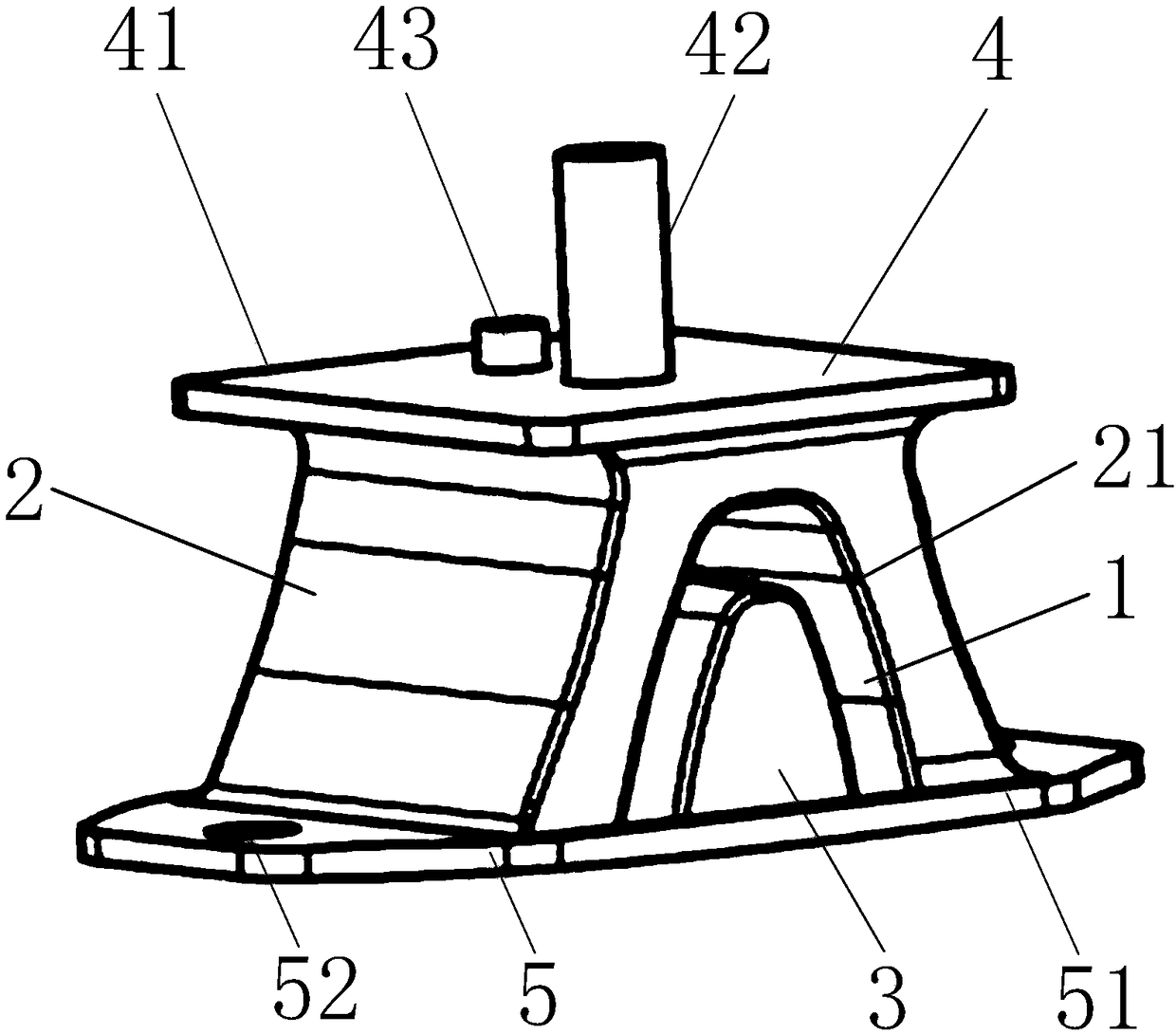
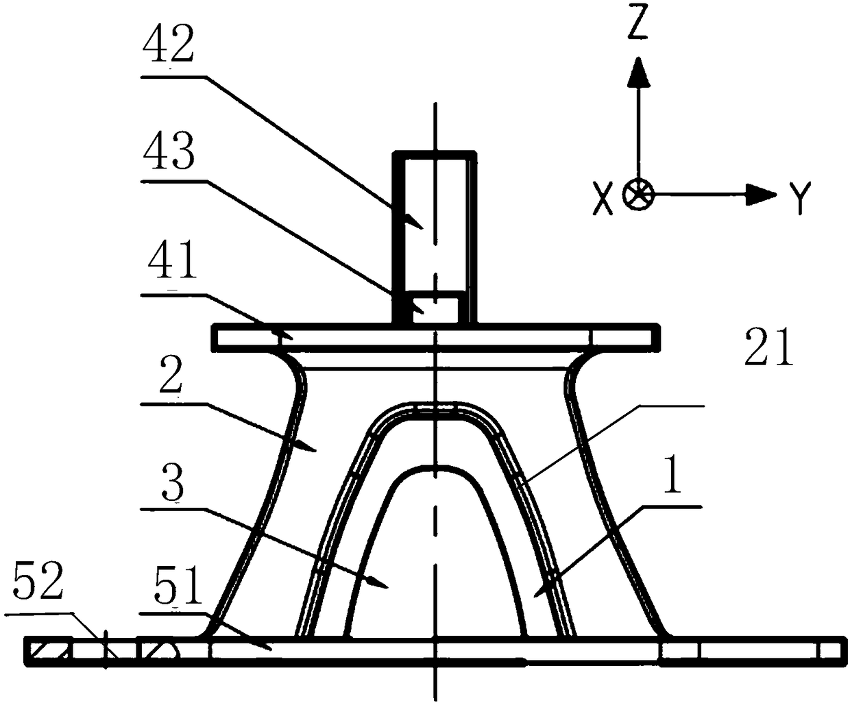
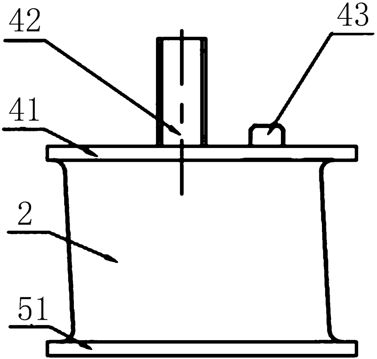
[0032] Figure 1 to Figure 4 Shows the embodiment of the engine suspension cushion assembly of the present invention, the engine suspension cushion assembly is arranged between the engine and the vehicle frame, used to reduce and control the transmission of engine vibration, and play the role of support and limit , in this embodiment, the engine suspension cushion assembly includes an upper mounting plate assembly 4, a lower mounting plate assembly 5 and a rubber assembly, the upper mounting plate assembly 4 is connected to the engine, the lower mounting plate assembly 5 is connected to the vehicle frame, and the rubber assembly Located between the upper mounting plate assembly 4 and the lower mounting plate assembly 5, the rubber assembly includes a rubber body...


PUM

PropertyMeasurementUnit
Shore hardnessaaaaaaaaaa

Abstract

The invention provides an engine mounting pad assembly. The assembly includes an upper installing plate assembly connected with an engine and a lower installing plate assembly connected to a vehicle frame. A rubber assembly is disposed between the upper installing plate assembly and the lower installing plate assembly. The rubber assembly includes a rubber body used for engine load and vibration reduction and a limit rubber block for limiting under extreme working conditions; the shore hardness of the rubber body is 40 degrees-60 degrees; and the shore hardness of the limit rubber block is more than 65 degrees. The engine mounting pad assembly has the advantages of a compact structure and effectively meeting requirements of support, limit and vibration isolation reduction.

Description

technical field [0001] The invention relates to the technical field of engine vibration reduction and isolation in motor vehicles, in particular to an engine suspension cushion assembly. Background technique [0002] At present, the automotive powertrain (engine + transmission) is usually installed on a suspension or a vibration isolator, and the suspension can be directly connected to the frame, or it can be placed on the sub-frame, and the sub-frame is passed through another suspension. Connect with the frame. During operation, if the vibration of the car powertrain cannot be effectively isolated, its vibration will be transmitted to various parts of the car to generate vibration and noise. When the vibration and noise reach the driver and passenger, their hearing and hearing will be seriously affected. comfort. [0003] The forces suffered by the engine in the working state mainly include static force (moment), transient and periodic excitation force (moment). In order ...

Claims


Application Information

Patent Timeline
Patent Type & Authority Applications(China)
IPC IPC(8): B60K5/12F16F1/36
CPCB60K5/1208F16F1/36
Inventor 罗旦钟海兵尹庆吴明珠郭春杰路英竹
Owner ZHUZHOU TIMES NEW MATERIALS TECH
Why Eureka
Try Eureka