Design method of width of effective surface of overflow brick for controlling average thickness of edge plate

A technology of average thickness and design method, applied in glass manufacturing equipment, manufacturing tools, glass forming, etc., can solve problems such as plate fluctuations, achieve the effects of guarantee and consistency, optimize the forming thickness distribution, and solve the forming lead plate fluctuations

Active Publication Date: 2018-12-14
IRICO DISPLAY DEVICES
View PDF4 Cites 5 Cited by
  • Summary
  • Abstract
  • Description
  • Claims
  • Application Information

AI Technical Summary

Problems solved by technology

This method adjusts the effective face width of the overflow brick so that the thickness of the side plate during the molding process of the glass substrate can meet the requirements; and then solves the problem of fluctuations in the lead plate caused by the thin side plate thickness during the molding process of the glass substrate

Method used


Image

  • Design method of width of effective surface of overflow brick for controlling average thickness of edge plate
  • Design method of width of effective surface of overflow brick for controlling average thickness of edge plate
  • Design method of width of effective surface of overflow brick for controlling average thickness of edge plate

Examples


Embodiment Construction

[0046] The present invention is described in further detail below in conjunction with accompanying drawing:

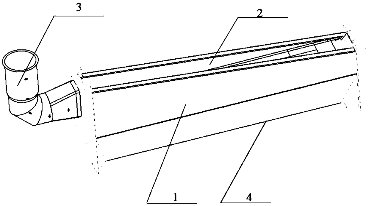
[0047] see figure 1 , The overflow system is composed of an overflow brick 1 and a glass liquid supply device 3 connected. There is an overflow groove 2 inside the overflow brick 1, and the bottom of the overflow brick 1 is the root of the overflow brick 1; when the glass substrate is manufactured by melting and overflowing, the glass melted by the glass melting furnace is melted in the forming process The liquid glass is supplied to the glass liquid supply device 3 in the melting overflow forming device, and overflows through both sides of the overflow brick 1 along the overflow groove 2, and forms a glass substrate from below the root 4 of the overflow brick 1.

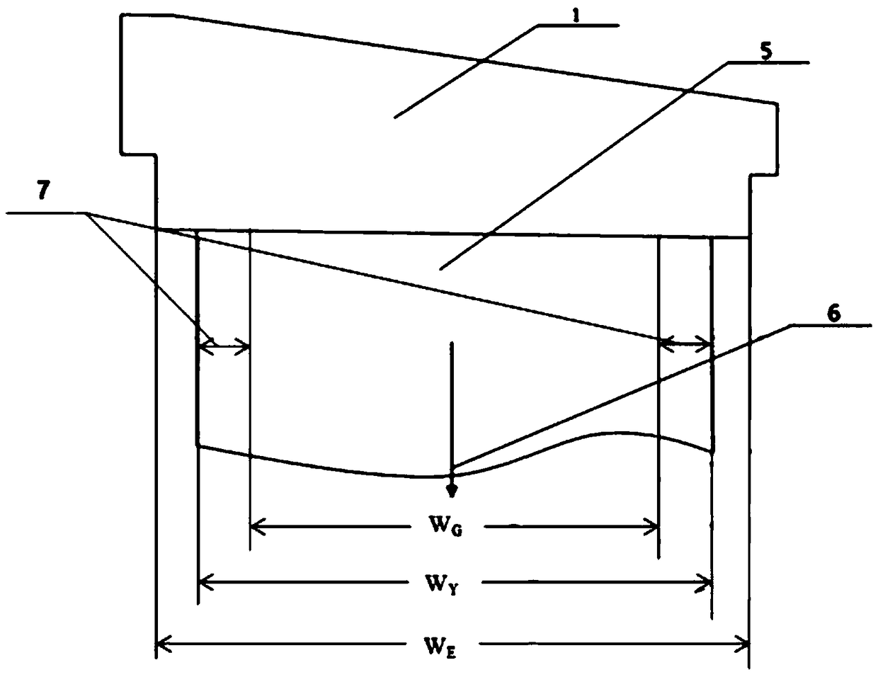
[0048] Such as figure 2 As shown, the lead plate is used as the forming basis of the glass substrate. During the process of down-molding the glass substrate, the formed glass substrate 5 moves downward al...


PUM

PropertyMeasurementUnit
thicknessaaaaaaaaaa
thicknessaaaaaaaaaa

Abstract

The invention discloses a design method of a width of an effective surface of an overflow brick for controlling the average thickness of an edge plate. According to the design method, started from a width WG of a target glass substrate, a width WY of a guide board of the glass substrate and a width WE of an effective surface of an overflow brick are calculated through introduction of a correctioncoefficient, and then an manufacturing average thickness TE of an edge plate of the glass substrate is calculated; an overflow coefficient for calculating the WE is continuously adjusted, so that thefinal TE meets design requirements; namely, the thickness TE of the edge plate of the glass substrate meets the design requirements through the design of the width WY of the guide plate and the widthWE of the effective surface. Process parameters are used for calculating other parameters of the overflow brick at the same time, and the process parameters comprise a guide plate speed V, an averageedge plate flow QE and an average edge plate mass ME, so that technological requirements of manufacturing stable guide plates in a glass substrate production line can be met. Through the design method, a problem of guide plate fluctuation of the field forming is effectively solved, and then the forming thickness distribution of the glass substrate manufacturing is optimized, so that production margins are increased from design, and consistency of thickness of the edge plate of the glass substrate is guaranteed.

Description

【Technical field】 [0001] The invention belongs to the field of glass substrate manufacturing, in particular to a method for designing the effective surface width of overflow bricks for controlling the average thickness of side plates. 【Background technique】 [0002] The glass substrates used in the production of flat panel displays such as TFT-LCD (Thin Film Transistor Display) and PDP (Plasma Display Panel) are manufactured by overflow down-drawing. In the forming process, molten glass melted by a glass melting furnace is supplied to Melt overflow down-draw molding device to manufacture. [0003] Display manufacturing requires ever larger glass substrates to increase productivity and reduce costs. The larger the glass substrate, the more difficult it is to produce, and the quality control of the glass substrate is more complicated. The overflow brick is one of the core components of the glass substrate manufacturing molding device. In terms of process, the fluid at the e...

Claims


Application Information

Patent Timeline
Patent Type & Authority Applications(China)
IPC IPC(8): C03B17/06
CPCC03B17/06
Inventor 李孟虎王答成
Owner IRICO DISPLAY DEVICES
Why Eureka
Try Eureka