
Restraining method for direct path waves of bi-static sonar system

A direct wave, bistatic technology, applied in the direction of sound wave re-radiation, radio wave measurement system, utilization of re-radiation, etc., can solve the problem of low beam resolution and achieve improved ability, low side lobe, and good tolerance Effect

Inactive Publication Date: 2018-12-14
HARBIN ENG UNIV
View PDF1 Cites 8 Cited by
  • Summary
  • Abstract
  • Description
  • Claims
  • Application Information

AI Technical Summary

Problems solved by technology

However, conventional beamforming with zero constraints is restricted by the Rayleigh limit, and the beam resolution is not high
To sum up, the existing direct wave suppression algorithms still have room for improvement, and how to effectively suppress the direct wave remains to be solved

Method used


Image

  • Restraining method for direct path waves of bi-static sonar system
  • Restraining method for direct path waves of bi-static sonar system
  • Restraining method for direct path waves of bi-static sonar system

Examples


Embodiment Construction

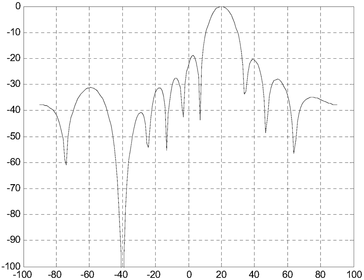
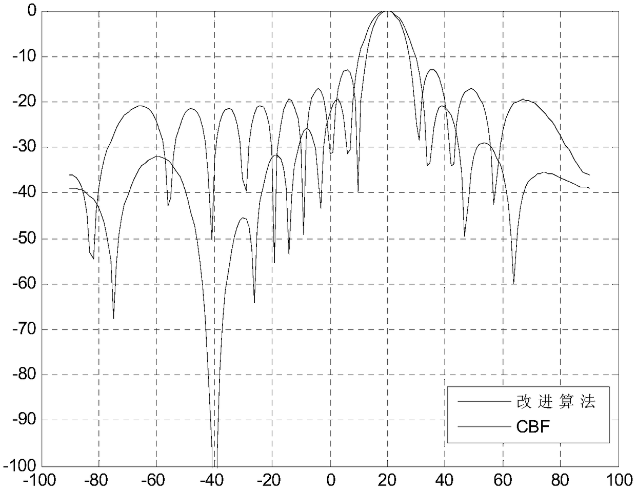
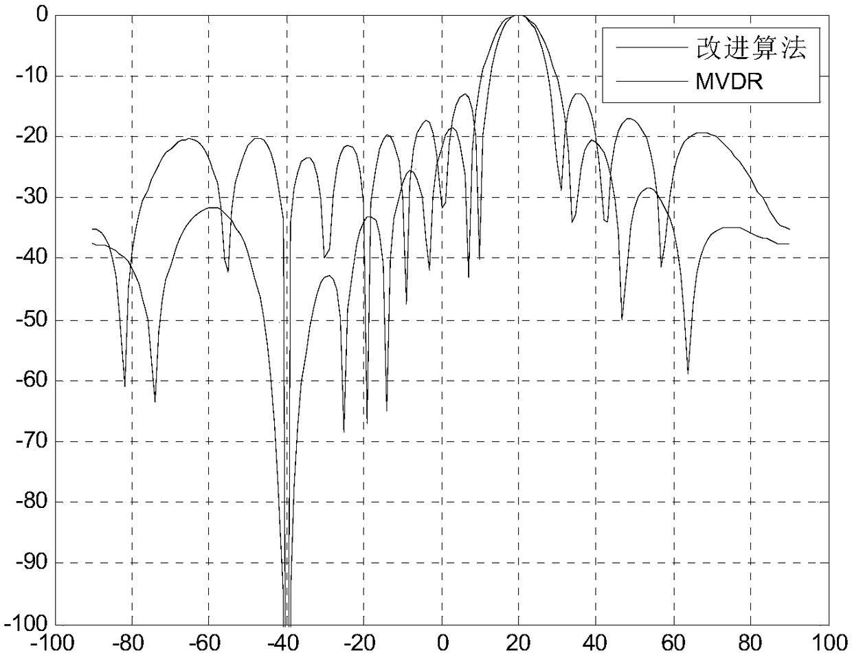
[0036] A bistatic sonar system direct wave suppression method of the present invention mainly includes two parts:

[0037] Step 1: Use the optimization model of the weighted sparse constraint Capon beamformer to obtain the optimal weight.

[0038]Step 2: Generate a null point in a fixed direction of the array pattern through the null-constrained beamforming technology, eliminate interference in this direction, and suppress coherent interference, thereby suppressing the direct wave.

[0039] As mentioned above, the step 1 includes the following content:

[0040] Step 1-1: Obtain the array time domain data of the signal, and the received signal model is

[0041]

[0042] where s j (t)(j=0,1,2,...J) represents the desired signal or interference signal at time t; θ j (j=0,1,2,...J) indicates the direction of arrival of the desired signal or interference signal; a(θ j )(j=0,1,2,...J) represents the steering vector of the desired signal or interference. n(t) represents the a...


PUM


Abstract

The invention provides a restraining method for direct path waves of a bi-static sonar system. The optimal weight is obtained by weighting an optimization model of a sparse constraint Capon wave beamformer; and a zero point is generated in the fixed direction of an array directional pattern through a zero point constraint wave beam forming technology, interference in the direction is eliminated,coherent interference is restrained, and thus the direct path waves are restrained. The bi-static sonar system is a bi-static configuration system, thus the receiving end can further receive the direct path waves with the amplitude being much larger than that of target echoes besides the target echoes. The deeper null can be generated beside the coherent interference, better tolerance can be achieved, low side lobes can be formed, and the capacity to SINR outputting by an array and steering vector angle mismatch resistance is improved.

Description

technical field [0001] The invention relates to a direct wave suppression method of a dual or multi-base sonar system. Specifically, when the direct wave and the target echo cannot be separated in the time domain, the method of effectively suppressing the direct wave in the air domain. Background technique [0002] my country is a country with both sea and land with an ocean area of ​​more than 3 million square kilometers. For a large ocean country like my country, safeguarding maritime rights and interests is crucial to the country's rise and security. Therefore, we need advanced marine technology. The advantages of the dual / multi-base sonar system are: strong anti-interference ability and large operating distance. Traditional sonar equipment mostly adopts single-base sonar with combined transceiver, while the bistatic sonar system adopts separate transceiver configuration, and the sound source (transmitter) and receiving equipment are separated by a long distance. Due t...

Claims


Application Information

Patent Timeline
IPC IPC(8): G01S15/06G01S7/539
Inventor 聂东虎梁佳乔钢周锋刘凇佐孙宗鑫马璐安思宇庞桐桐马永铮
Owner HARBIN ENG UNIV
Learn More