High rigidity retractable parabolic cylindrical antenna

A parabolic, high-rigidity technology, used in antennas, folded antennas, antenna components, etc., can solve problems such as poor rigidity and stability, difficult to divide triangular folding units, and vibration.

Active Publication Date: 2018-12-14
NANJING UNIV OF AERONAUTICS & ASTRONAUTICS
View PDF12 Cites 9 Cited by
  • Summary
  • Abstract
  • Description
  • Claims
  • Application Information

AI Technical Summary

Problems solved by technology

At present, the combination of cable-rod deployable structure and metal reflective net is mainly used to meet the above requirements. However, unlike the common rotating parabolic antenna with central axis symmetry, the parabolic antenna is symmetrical about the axis of symmetry "dual axis" and the focus is always It is difficult to decompose the stretching motion of the line, especially it is difficult to divide into stable triangular stretching units
In addition, as the antenna diameter increases, it is susceptible to large-scale vibration caused by external disturbances. In order to ensure the stability of the antenna structure, it is generally necessary to lock the antenna. At present, it mainly relies on structural self-locking or additional locking devices. The self-locking method has the advantages of simple mechanism, good reliability, and small mass, but only relying on the one-way self-locking structure, when the mechanism is disturbed by impact or the like, it is easy to break away from the self-locking state and cause vibration
Therefore, the common configuration of this type of antenna has problems such as poor stiffness and stability, which is not conducive to the further increase of the antenna aperture and long-term reliable on-orbit work

Method used


Image

  • High rigidity retractable parabolic cylindrical antenna
  • High rigidity retractable parabolic cylindrical antenna
  • High rigidity retractable parabolic cylindrical antenna

Examples


Embodiment Construction

[0019] The high-rigidity retractable parabolic cylindrical antenna of the present invention will be further described in detail below in conjunction with the accompanying drawings. These drawings are all simplified schematic diagrams, and only illustrate the basic structure of the present invention in a schematic manner.

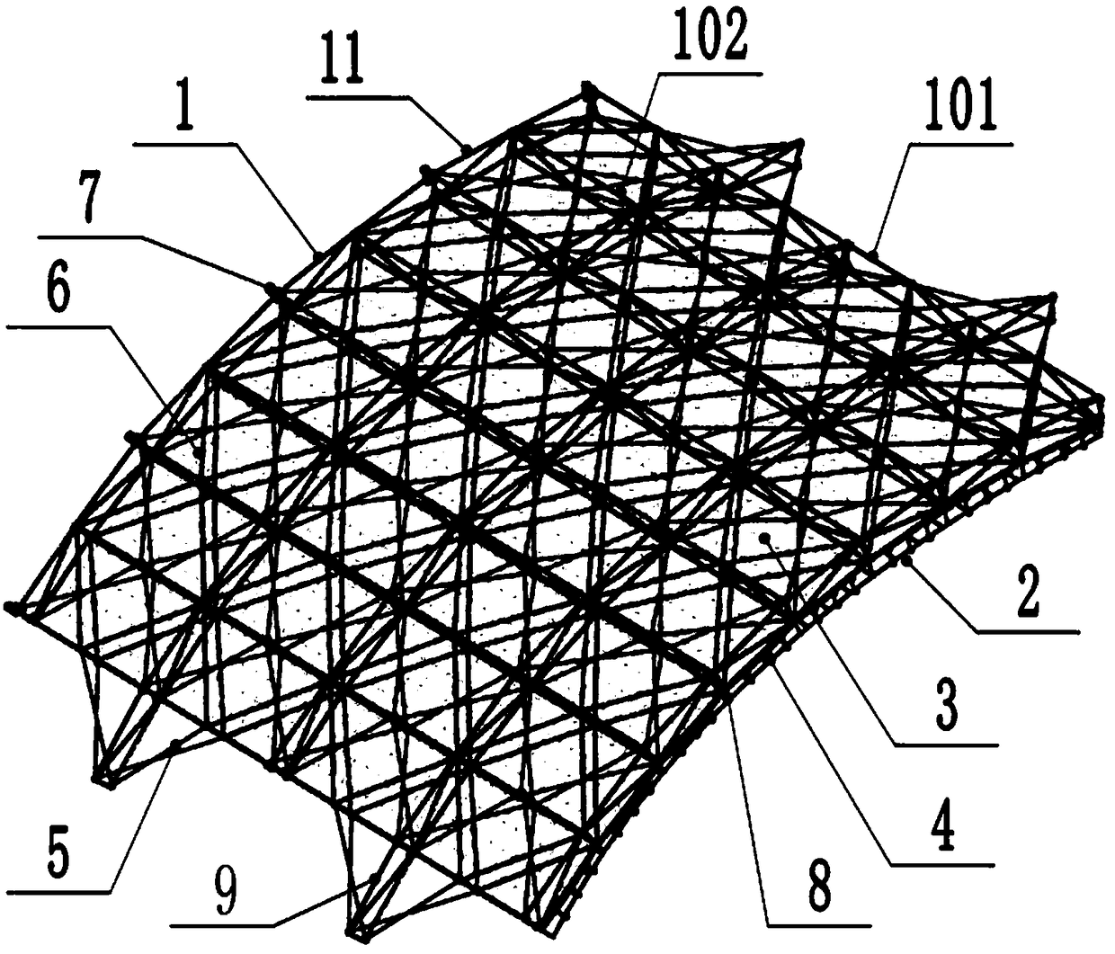
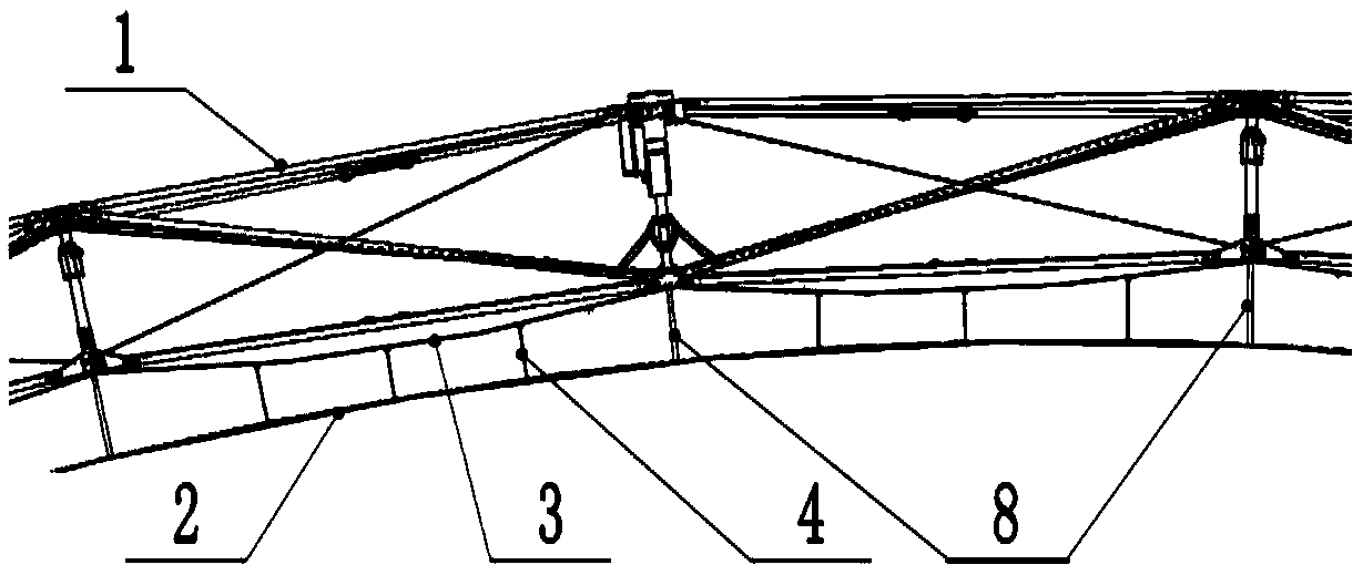
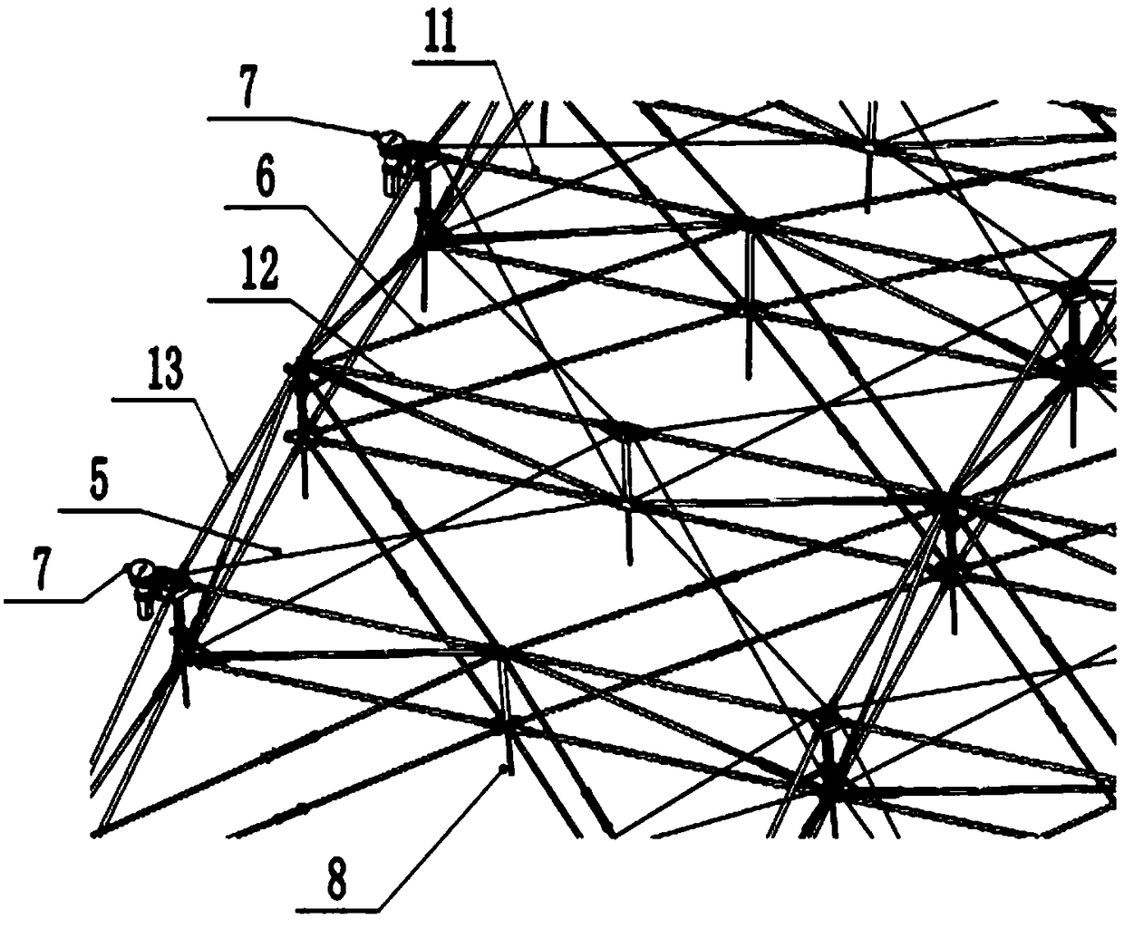
[0020] The high-rigidity retractable parabolic cylindrical antenna designed by the present invention, such as Figure 1-6 As shown, it includes: an expandable support frame 1, a reflection net 2, a balance net 3, a vertical cable 4, a tension cable 5, a diagonal brace 6, a slow release device 7, and a mesh brace 8. The support frame 1 includes a cylindrical surface folding module 101, an auxiliary surface folding module 102, and an arc surface folding module 103. The cylindrical surface folding module 101, the auxiliary surface folding module 102, and the arc surface folding module 103 are composed of a plurality of The basic folding unit 201 is connected a...


PUM


Abstract

A high-rigidity retractable parabolic cylindrical antenna is disclosed, comprises a deployable support frame, a reflective net, a balancing net, a vertical cable, a tension cable, an inclined strut, aslow release device, a net strut, and the deployable support frame comprises a cylindrical folding module, an auxiliary surface folding module, an arc surface folding module, a cylindrical surface folding module and an auxiliary surface folding module, wherein the arc surface folding module is composed of a plurality of basic folding units; The invention realizes the decomposition of the parabolic cylinder into a plurality of triangular prism folding units and the interlocking between the mechanisms after the antenna is deployed, The parabolic cylindrical antenna has the advantages of high rigidity and high stability structure after the parabolic cylindrical antenna is reliably folded and unfolded and locked. In addition, the antenna of the invention is a regular rectangular body in a folded configuration, which is convenient for receiving and installing, and can be used for realizing the large-caliber parabolic cylindrical antenna with long-term reliable on-orbit working capability.

Description

technical field [0001] The invention relates to a high-rigidity retractable parabolic cylinder antenna, which belongs to the technical field of satellite antenna structures. Background technique [0002] The linear array feed parabolic cylinder antenna can form simultaneous multi-directional beam clusters in a certain azimuth plane and elevation plane. Within a wide frequency band, it can quickly correspond to various targets in different azimuths and different elevation angles. Double targeting of frequency and direction, and the ability to combine space power, its application in the field of space-borne antennas has been paid more and more attention to. Like other large-scale space-borne antennas, it is generally required to have light weight due to the limitation of carrying space and capacity. Features such as flexibility and expandability. At present, the combination of cable-rod deployable structure and metal reflective net is mainly used to meet the above requirement...

Claims


Application Information

Patent Timeline
Patent Type & Authority Applications(China)
IPC IPC(8): H01Q1/12H01Q1/08H01Q15/14
CPCH01Q1/08H01Q1/1207H01Q15/14
Inventor 陈金宝林飞陈传志宋志成董自瑞魏君戴宇航刘虎林郭芸芸陈佳伟袁英男周金华王宸汪捷
Owner NANJING UNIV OF AERONAUTICS & ASTRONAUTICS
Why Eureka
Try Eureka