A microwave or millimeter wave amplitude and phase control circuit based on a directional coupler

A technology of phase control circuit and directional coupler, which is applied in the direction of circuits, electrical components, antenna arrays, etc., can solve the problems of complex structure, high cost, and large scale of traditional amplitude and phase control circuits, and achieve simple structure, low circuit cost, Inexpensive effect

Inactive Publication Date: 2018-12-14
ZHEJIANG UNIV
View PDF7 Cites 0 Cited by
  • Summary
  • Abstract
  • Description
  • Claims
  • Application Information

AI Technical Summary

Problems solved by technology

[0004] 1. The structure is complex, and it is necessary to introduce a phase shifter to modulate the phase of the signal, and an attenuator to modulate the amplitude of the signal, which makes the traditional amplitude and phase control circuit larger in scale
[0005] 2. The cost of TR components in the existing millimeter wave band is relatively high

Method used


Image

  • A microwave or millimeter wave amplitude and phase control circuit based on a directional coupler
  • A microwave or millimeter wave amplitude and phase control circuit based on a directional coupler
  • A microwave or millimeter wave amplitude and phase control circuit based on a directional coupler

Examples


Embodiment Construction

[0063] Attached below Figure 4 Examples further illustrate the present invention.

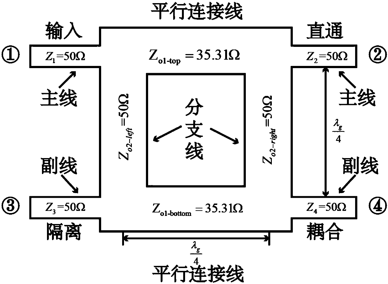
[0064] The implementation of the present invention takes the square branch directional coupler as an example to illustrate the working principle of the present invention:

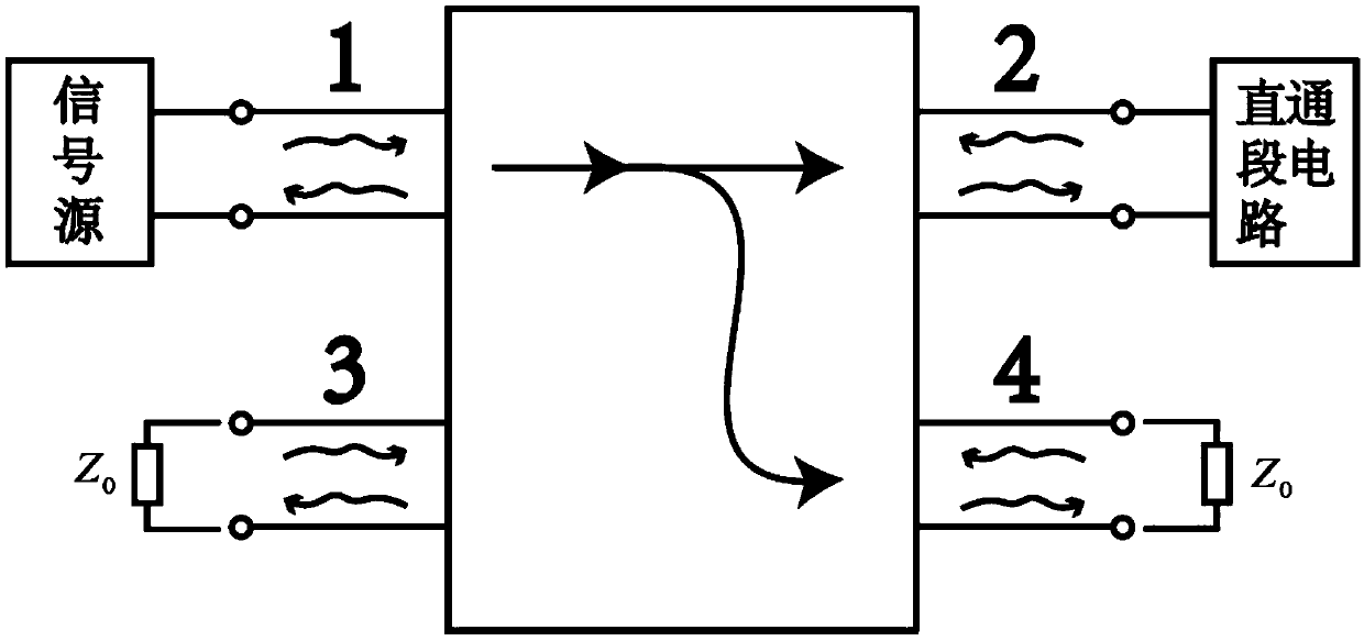
[0065] Set the target as follows: when the other three ports 2, 3, and 4 match, the reflection coefficient S of port 1 11 ≤-30dB, forward transmission coefficient S from port 1 to port 2 21 ≥-3.2dB, forward transmission coefficient S from port 1 to port 3 31 ≤-30dB, forward transmission coefficient S from port 1 to port 4 41 ≥-3.2dB, the operating frequency of the directional coupler is around 34.0GHz, and the microstrip size parameters of the directional coupler are optimized.

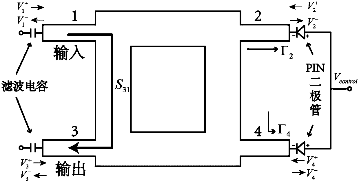
[0066] Then, add a PIN diode at the through port and the coupling port. The PIN diode is MA4GP907, and a DC bias voltage V is introduced at the same time. control . Finally, draw out the directional coupler |S 31 |, ∠S 31 The change curve o...


PUM


Abstract

The invention discloses a microwave or millimeter wave amplitude and phase control circuit based on a directional coupler. By adding a PIN transistor or a JFET transistor operating in the microwave ormillimeter band to the through port and coupling port of a conventional directional coupler, By controlling the DC bias voltage across the positive and negative terminals of the PIN transistor or theDC bias voltage from the gate g of the JFET transistor to the two terminals of the source s, the reflection coefficient of the through port and the coupling port can be changed, and the S-parameter distribution of the four-port network of the directional coupler can be influenced. The invention realizes the function of amplitude modulation and phase modulation of the radio frequency signal in thecircuit at the same time, The invention reduces the dependence of millimeter band communication on high-cost TR module, solves the engineering problem of automatic control and adjustment of RF signalamplitude and phase in microwave or millimeter wave field, simplifies the circuit, avoids the combination of analog devices in traditional amplitude and phase control circuit, and reduces the cost.

Description

technical field [0001] The invention relates to the field of microwave and millimeter wave amplitude and phase controllable circuits, in particular to a microwave or millimeter wave amplitude and phase control circuit based on a directional coupler. Background technique [0002] As we all know, the communication frequency band resources used in the world are very scarce at present, but the resources of the millimeter wave frequency band are very rich. At the same time, as 5G communication technology gradually enters the application era, the demand for antenna architectures in the millimeter-wave band and back-end RF processing circuits is gradually increasing. However, some existing microwave and millimeter-wave radio frequency circuit architectures are large-scale , The high cost. The main bands of 5G communication research are concentrated between 9.9 and 86 GHz, and based on LTE technology, research on network coverage is carried out. In the 28GHz millimeter wave band, ...

Claims


Application Information

Patent Timeline
Patent Type & Authority Applications(China)
IPC IPC(8): H01Q3/26H01Q21/00H01Q23/00
CPCH01Q3/26H01Q21/00H01Q23/00
Inventor 王赫冉立新
Owner ZHEJIANG UNIV
Why Eureka
Try Eureka