Supercharge Your Innovation With Domain-Expert AI Agents!

Electrode unit, power transmitting device, power receiving device, electronic device, vehicle, and wireless power transmission system

一种无线电力传输、电极单元的技术,应用在电路装置、电气元件、运输和包装等方向,能够解决电场泄漏、电子设备误动作等问题,达到抑制电场的泄漏、减少误动作的效果

Inactive Publication Date: 2018-12-14
PANASONIC INTPROP MANAGEMENT CO LTD
View PDF4 Cites 4 Cited by
  • Summary
  • Abstract
  • Description
  • Claims
  • Application Information

AI Technical Summary

Problems solved by technology

[0007] In the existing wireless power transmission based on the electric field coupling method, electric field leakage may occur around a pair of power transmitting electrodes or a pair of power receiving electrodes, causing malfunction of surrounding electronic devices, etc.

Method used


Image

  • Electrode unit, power transmitting device, power receiving device, electronic device, vehicle, and wireless power transmission system
  • Electrode unit, power transmitting device, power receiving device, electronic device, vehicle, and wireless power transmission system
  • Electrode unit, power transmitting device, power receiving device, electronic device, vehicle, and wireless power transmission system

Examples


Embodiment approach 1

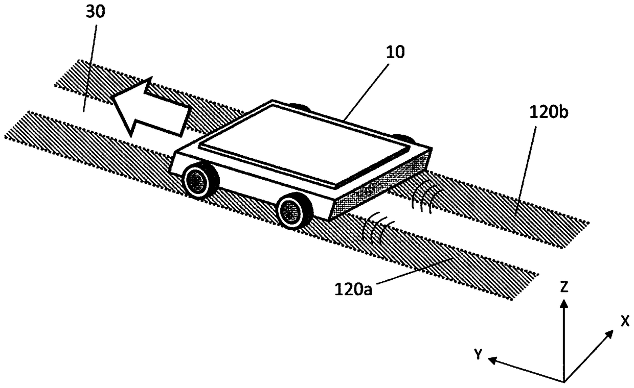
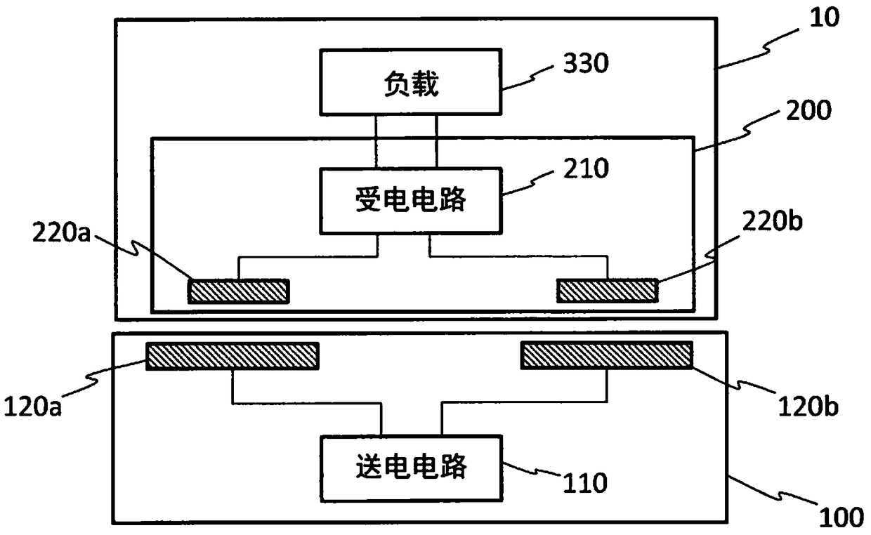
[0120] Figure 4 is a diagram schematically showing the wireless power transmission system in Embodiment 1 of the present disclosure. exist Figure 4 In the system shown, with figure 1The illustrated system similarly transmits electric power wirelessly from a power transmitting device having a pair of power transmitting electrodes disposed below or above the ground to a transfer robot 10 having a pair of power receiving electrodes. The pair of power transmission electrodes are the first power transmission electrode 120a and the second power transmission electrode 120b. The second power transmission electrode 120b is arranged apart from the first power transmission electrode 120a in the first direction (X direction in this example) along the surface of the first power transmission electrode 120a.

[0121] The power transmission electrodes 120a and 120b extend in parallel along the ground. The power transmission electrodes 120a and 120b are arranged on substantially the same...

Embodiment approach 2

[0186] Next, an embodiment in which the transfer robot 10 includes electronic equipment will be described.

[0187] Various electronic devices can be mounted on the transfer robot 10 . For example, it is possible to mount a sensor that detects movable objects such as people, animals, or other moving objects in the surroundings. Alternatively, an electronic device such as a sensor that reads a mark for position detection arranged on the ground can be mounted.

[0188] Figure 21 It is a diagram showing an example of a factory in which a plurality of markers for position detection are arranged on the ground. In this example, marks 50 including two-dimensional codes such as a QR code (registered trademark), for example, are given to a plurality of positions on the ground. The transfer robot 10 is provided with an imaging element (that is, an image sensor) for reading the mark 50 on the bottom surface of the casing. The two-dimensional code of the marker 50 indicates the coord...


PUM


Abstract

The present invention provides an electrode unit, a power transmitting device, a power receiving device, an electronic device, a vehicle, and a wireless power transmission system, with which it is possible to suppress the electric field leakage around power transmitting electrodes or power receiving electrodes. The electrode unit is used in a power transmitting device or a power receiving device of a wireless power transmission system based on an electric field coupling method. The electrode unit includes: a first electrode to which a first voltage is applied when power is transferred; a second electrode to which a second voltage antiphase to the first voltage is applied when power is transferred; and a third electrode spaced apart from the first and second electrodes, the third electrodehaving a third voltage whose amplitude is less than amplitudes of the first and second voltages when power is transferred. The first and second electrodes are arranged along an electrode installationplane. At least a portion of the third electrode does not overlap the first and second electrodes as viewed from a direction perpendicular to the electrode installation plane.

Description

technical field [0001] The present disclosure relates to an electrode unit, a power transmission device, a power reception device, electronic equipment, a mobile body, and a wireless power transmission system. Background technique [0002] In recent years, development of a wireless power transmission technology that transmits electric power wirelessly, that is, without contact, has been underway for mobile devices such as mobile phones and electric vehicles. In the wireless power transmission technology, there are methods such as an electromagnetic induction method and an electric field coupling method. Among them, the wireless power transmission system based on the electric field coupling method wirelessly transmits AC power from a pair of power transmitting electrodes to a pair of power receiving electrodes in a state where a pair of power transmitting electrodes and a pair of power receiving electrodes face each other. Such a wireless power transmission system based on a...

Claims


Application Information

Patent Timeline
Patent Type & Authority Applications(China)
IPC IPC(8): H02J50/05
CPCH02J50/05H02J50/70B66B7/00H02J50/80H02J50/12
Inventor 菅野浩
Owner PANASONIC INTPROP MANAGEMENT CO LTD
Features
  • R&D
  • Intellectual Property
  • Life Sciences
  • Materials
  • Tech Scout
  • Unparalleled Data Quality
  • Higher Quality Content
  • 60% Fewer Hallucinations
Learn More