Device for holding vehicle sliding door at full-open position

A fully open position and holding device technology, applied in the direction of power devices, electric power devices, pneumatic power devices, etc., can solve the problems of poor convenience, disadvantages, and inability to close sliding doors, etc., to achieve high holding force, Good effect of convenience

Inactive Publication Date: 2002-09-04
MITSUI KINZOKU ACT +1
View PDF1 Cites 0 Cited by
  • Summary
  • Abstract
  • Description
  • Claims
  • Application Information

AI Technical Summary

Problems solved by technology

[0008] figure 1, figure 2 The holding device shown has a very high holding force due to the use of the pawl H to keep the stop plate G and the striker J engaged, but the stop plate cannot be released when the opening handle of the slidi

Method used


Image

  • Device for holding vehicle sliding door at full-open position
  • Device for holding vehicle sliding door at full-open position
  • Device for holding vehicle sliding door at full-open position

Examples


Embodiment Construction

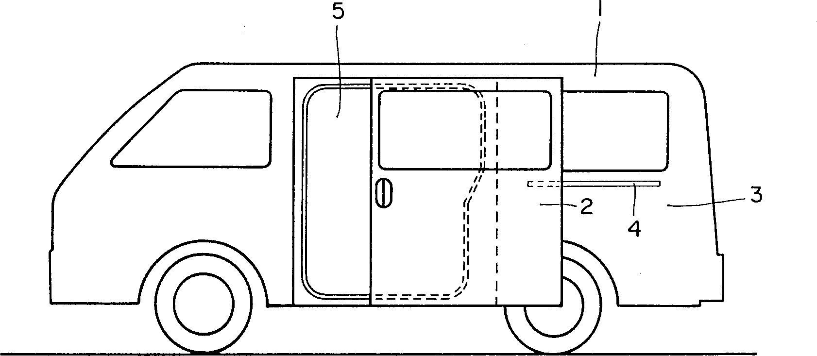
[0021] An embodiment of the present invention is described with reference to the accompanying drawings. Such as image 3 As indicated, the vehicle body 1 has a sliding door 2 , which is slidably supported on guide rails 4 fastened to a rear side panel 3 of the vehicle body 1 . The sliding door 2 can move substantially parallel to the side of the vehicle body 1 when it is between the position where the side panel 3 opens and closes the inlet and outlet 5 of the vehicle body 1 .

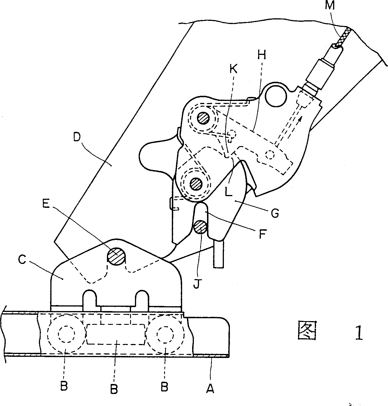
[0022] On the above-mentioned sliding door 2, fixed such as Figure 4~6 In the shown connection bracket 6 , a roller bracket 8 is rotatably attached to the front end portion of the connection bracket 6 via a shaft 7 . A plurality of rollers 9 that can slide freely on the above-mentioned guide rail 4 are supported by shafts on the roller bracket 8 .

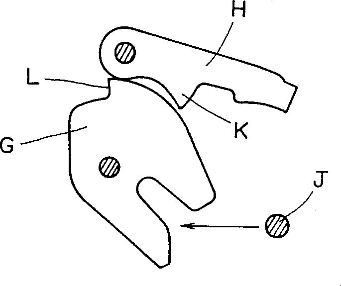
[0023] A holding device 10 for holding the sliding door 2 at a fully open position is attached to the connecting bracket 6 . The holding device 10 inc...


PUM


Abstract

The full-open position maintaining device for a sliding door of a vehicle includes: a striker pin fixed on the vehicle body; a ratchet that can be rotatably arranged on the above-mentioned sliding door, and the pawl is provided with the above-mentioned The U-shaped bayonet that is matched with the striker pin, the above-mentioned pawl also has the first position of the non-coordination of the above-mentioned U-shaped bayonet with respect to the above-mentioned striker pin and the second position where the above-mentioned U-shaped bayonet is matched with the above-mentioned striker pin; An elastic force means is provided between the above-mentioned pawl and the above-mentioned sliding door to hold the above-mentioned pawl at any one of the above-mentioned first position and the above-mentioned second position by elastic force, and the elastic force device is in direct contact with the above-mentioned pawl.

Description

[0001] The technical field of the invention [0002] The present invention relates to a holding device for a sliding door of a vehicle installed on a vehicle body and is particularly related to a device for holding the sliding door in a fully open position. Background technique [0003] In the prior art, the sliding door is equipped with rollers that can slide freely in the guide rails installed on the side of the vehicle body, so that the sliding door can be paralleled between the fully open position and the fully closed position relative to the side of the vehicle body. move. [0004] In the above sliding door, means for holding the sliding door at the fully closed position and means for holding the sliding door at the fully open position are provided. The present invention relates to the latter holding device described above. [0005] The latter holding device is composed of a fully elastic leaf spring arranged at the end of the guide rail. When the sliding door is moved ...

Claims


Application Information

Patent Timeline
IPC IPC(8): B60J5/06E05D15/10B60K17/04B60J5/00B60K1/04B60K6/20B60K6/24B60K6/26B60K6/36B60K6/38B60K6/383B60K6/387B60K6/40B60K6/48B60K6/543B60K17/02E05B15/04E05B65/08E05C17/46E05C17/60
CPCB60K1/04B60K6/36B60K6/383B60K6/40B60K6/48B60K6/543B60K17/02B60W30/18036B60Y2200/12B60L50/16B60L50/66E05B65/0811E05B83/40E05B85/243E05B2015/0413E05B2015/0458E05C17/60E05D13/04E05Y2900/531F16H2200/0034Y02T10/62Y02T10/70Y02T10/7072Y10S903/903Y10S903/905Y10S903/906Y10S903/909Y10S903/912Y10S903/913Y10S903/914Y10S903/918Y10S903/951Y10T292/1051Y10T292/1062E05D15/10
Inventor 水木哲郎P·道灵加藤恭英小桥贤司
Owner MITSUI KINZOKU ACT
Why Eureka
Try Eureka