High-effective filter press with diaphragm filter plates

A membrane filter plate and filter press technology, applied in filtration separation, separation methods, chemical instruments and methods, etc., can solve the problem that the material cannot be fully squeezed, the filter cake is not easy to be separated by filter cloth, and the one-time processing capacity is small, etc. problems, to achieve the effect of easy to peel off the filter cloth, saving processing time, and complete solid-liquid separation

Active Publication Date: 2018-12-18
浙江胜达祥伟化工有限公司
View PDF12 Cites 1 Cited by
  • Summary
  • Abstract
  • Description
  • Claims
  • Application Information

AI Technical Summary

Problems solved by technology

[0003] When the filter press in the prior art is in use, when too much material is added, the filtered filter cake will be very thick, and the material in the center position cannot be fully squeezed, resulting in a large water content in the filter cake , the extrusion time is prolonged, and when too little material is added, the work efficiency will be greatly reduced, and the thickness of the filter cake produced by extrusion is relatively thin, and the filter cake is not easy to separate from the filter cloth. Therefore, in actual production, people use diaphragm filter press. The method is a filter press with a layer of elastic membrane installed between the filter plate and the filter cloth. After the feeding is completed, the high-pressure fluid or gas medium is filled into the diaphragm plate, and the filter cake is pressed through the elastic mold. Further dehydration of the filter cake, but on the one hand, this production method has a small amount of one-time treatment, which reduces the work efficiency. At the same time, the filter cake still needs to be scraped off after the first separation to prevent the filter cake from adhering to the filter cloth. Separation speed affects, in order to solve this problem, the present invention provides the following technical solutions

Method used


Image

  • High-effective filter press with diaphragm filter plates
  • High-effective filter press with diaphragm filter plates
  • High-effective filter press with diaphragm filter plates

Examples


Embodiment Construction

[0027] The following clearly and completely describes the technical solutions in the embodiments of the present invention. Obviously, the described embodiments are only some of the embodiments of the present invention, but not all of them. Based on the embodiments of the present invention, all other embodiments obtained by persons of ordinary skill in the art without creative efforts fall within the protection scope of the present invention.

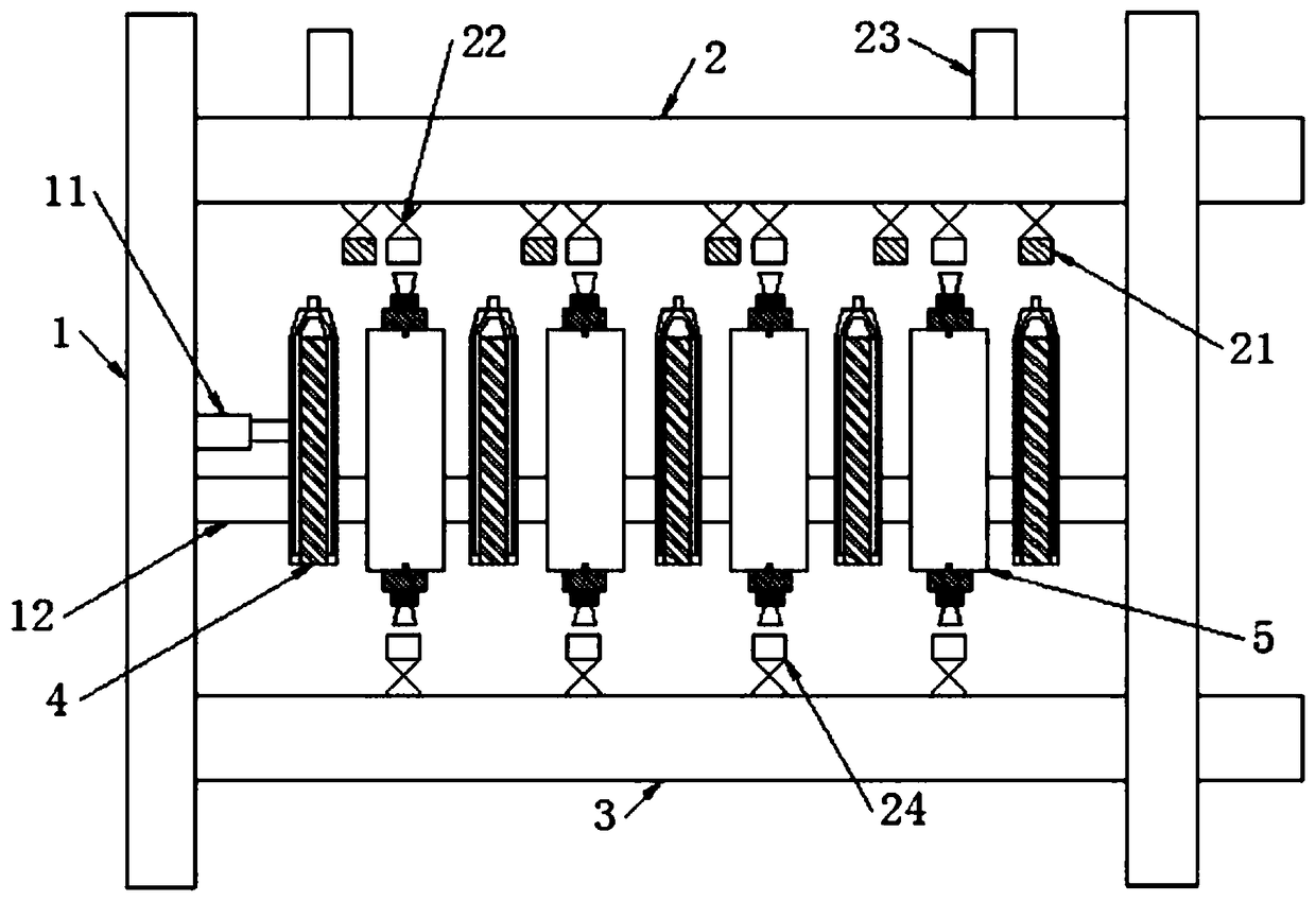
[0028] A high-efficiency membrane filter plate filter press, such as figure 1 As shown, including the support 1, the support 1 is slidably provided with an upper end feed pipe 2 and a lower end feed pipe 3, the upper end feed pipe 2 is connected with a row of electromagnetic valves 22, and the adjacent electromagnetic valves 22 are respectively connected to the The feed port 24 and the pressurized feed port 21 are connected to the pressurized feed port 21 on the electromagnetic valve 22 located at both ends, and a row of electromagnetic ...


PUM


Abstract

A high-effective filter press with diaphragm filter plates includes: a support, on which a top feeding pipe and a bottom feeding pipe are slidingly arranged. A row of electromagnetic valves are connected to the top feeding pipe, wherein a feeding port and a pressurized feeding port are respectively on each adjacent electromagnetic valve. A row of electromagnetic valves are connected to the bottomfeeding pipe, wherein feeding ports are connected to the electromagnetic valves on the bottom feeding pipe. The top feeding pipe and the bottom feeding pipe are respectively connected with driving apparatuses. Sliding bars are installed on the support, wherein pressurizing members and filtering members are alternately connected to the sliding bars in a sliding manner. A pressurizing member on oneend of the sliding bars is fixed to the sliding bars while an air cylinder is connected to a pressurizing member on the other end of the sliding bars. A first connector on each filtering member and asecond connector on each pressurizing member are connected to each other through a yoked connection rod. The filter press can completely separate solids and liquid, wherein a filter cake is easy to dry and strip off from a filter cloth. The filter press is large in one-time processing capacity and is free of removing the filter cake before every feeding operation. The filter press saves a large quantity of treatment time and can increase productivity of enterprises.

Description

technical field [0001] The invention belongs to the technical field of solid-liquid separation equipment, and in particular relates to a high-efficiency membrane filter plate filter press. Background technique [0002] The filter press is a solid-liquid separation equipment commonly used in industrial production. When in use, the solid-liquid suspension is added to the filter cloth, and then the liquid in the solid-liquid suspension is dialyzed out by squeezing the filter cloth, and the The filter cake formed by the solid residue stays in the filter cloth, so as to realize efficient solid-liquid separation, and then the filter cake or filtrate can be continued to be processed as required. [0003] When the filter press in the prior art is in use, when too much material is added, the filtered filter cake will be very thick, and the material in the center position cannot be fully squeezed, resulting in a large water content in the filter cake , the extrusion time is prolonged...

Claims


Application Information

Patent Timeline
IPC IPC(8): B01D25/168B01D25/30
CPCB01D25/164B01D25/30
Inventor 王玉凯
Owner 浙江胜达祥伟化工有限公司
Why Eureka
Try Eureka