Centrifugal separator with wall scraping function

A centrifugal separator and functional technology, applied in the field of centrifuges, can solve problems such as the reduction of centrifuge centrifugation effect, achieve the effect of improving centrifugation efficiency and ensuring centrifugation effect

Inactive Publication Date: 2018-12-18
HEFEI OUYU AUTOMATION CO LTD
View PDF6 Cites 0 Cited by
  • Summary
  • Abstract
  • Description
  • Claims
  • Application Information

AI Technical Summary

Problems solved by technology

[0002] The centrifuge is mainly used to separate the solid particles in the suspension from the liquid; or to separate two different densities and immiscible liquids in the emulsion; it can also be used to remove the liquid in the wet solid, special Ultra-speed tube separators can also separate gas mixtures of different densities, such as enrichment and separation of gaseous UF6; using the characteristics of different sedimentation velocities of solid particles of different densities or particle sizes in liquids, some decanter centrifuges can also separate solids Particles are classified according to density or particle size. Centrifugal separators are widely used in chemical industry, petroleum, food, pharmaceuticals, mineral processing, coal, water treatment and shipping. In the waste recycling process, the solid and liquid in the waste are often mixed , which often leads to the adhesion of waste to the inner wall of the centrifuge, which reduces the centrifugal effect of the centrifuge

Method used


Image

  • Centrifugal separator with wall scraping function
  • Centrifugal separator with wall scraping function

Examples


Embodiment Construction

[0017] The following will clearly and completely describe the technical solutions in the embodiments of the present invention with reference to the accompanying drawings in the embodiments of the present invention. Obviously, the described embodiments are only some, not all, embodiments of the present invention. All other embodiments obtained by persons of ordinary skill in the art based on the embodiments of the present invention belong to the protection scope of the present invention.

[0018] According to an embodiment of the present invention, a centrifugal separator with a scraping function is provided.

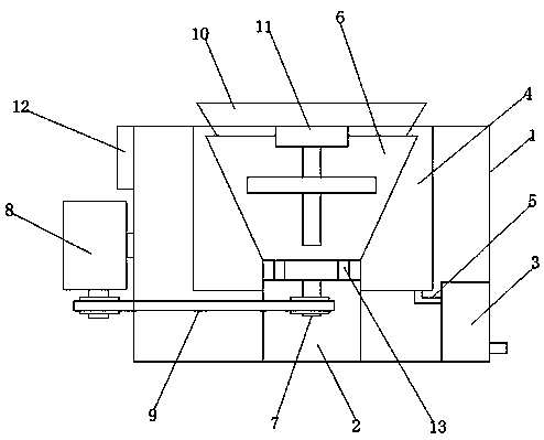
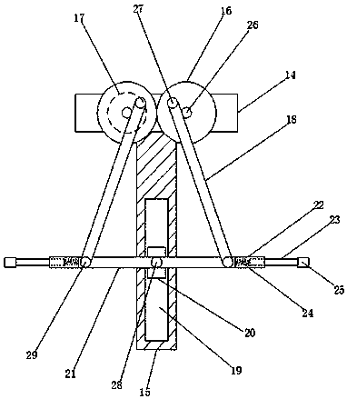
[0019] Such as Figure 1-2 As shown, the centrifuge with wall scraping function according to the embodiment of the present invention includes a body 1, a deodorizing box 2 is arranged inside the body 1, and a disinfection box 3 is arranged on one side of the deodorizing box 2. The top of the deodorizing box 2 is provided with a separation chamber 4, the separation chamb...


PUM


Abstract

The invention discloses a centrifugal separator with a wall scraping function. The centrifugal separator with the wall scraping function comprises a machine body, a deodorization box is arranged inside the machine body, a disinfection box is arranged on one side of the deodorization box, and a separation cavity is formed in the top end of the deodorization box; the separation cavity is connected with the disinfection box through a pipeline, a rotating drum is arranged inside the separation cavity, and a transmission shaft is arranged at the bottom end of the rotating drum; a motor I is arranged on one side of the machine body, an output shaft of the motor I is connected with the transmission shaft through a belt, and a feeding port is formed in the top end of the rotating drum; and a wallscraping mechanism cooperating with the rotating drum is arranged at the top end of the inner wall of the separation cavity, an operation panel is arranged on one side of the machine body and locatedabove the motor I, and a plurality of discharging ports are formed in the bottom end of the rotating drum. The centrifugal separator with the wall scraping function has the beneficial effects that thepurpose of scraping the inner wall of the rotating drum is achieved, then the centrifugal effect of the centrifugal separator is ensured, and then the centrifugal efficiency of the centrifugal separator is improved.

Description

technical field [0001] The invention relates to the technical field of centrifuges, in particular to a centrifuge with a scraping function. Background technique [0002] The centrifuge is mainly used to separate the solid particles in the suspension from the liquid; or to separate two different densities and immiscible liquids in the emulsion; it can also be used to remove the liquid in the wet solid, special Ultra-speed tube separators can also separate gas mixtures of different densities, such as enrichment and separation of gaseous UF6; using the characteristics of different sedimentation velocities of solid particles of different densities or particle sizes in liquids, some decanter centrifuges can also separate solids Particles are classified according to density or particle size. Centrifugal separators are widely used in chemical industry, petroleum, food, pharmaceuticals, mineral processing, coal, water treatment and shipping. In the waste recycling process, the sol...

Claims


Application Information

Patent Timeline
Patent Type & Authority Applications(China)
IPC IPC(8): B04B5/10B04B15/06
CPCB04B5/10B04B15/06
Inventor 李方奇张鹏
Owner HEFEI OUYU AUTOMATION CO LTD
Why Eureka
Try Eureka