
Feeding device of automatic mechanical arm of numerical control machine tool

A technology of CNC machine tools and feeding devices, which is applied in the directions of feeding devices, positioning devices, storage devices, etc., can solve the problems of free adjustment of device height, and achieve the effect of improving the scope of application and preventing shaking.

Inactive Publication Date: 2018-12-18
肇庆高新区黑阳科技有限公司
View PDF0 Cites 2 Cited by
  • Summary
  • Abstract
  • Description
  • Claims
  • Application Information

AI Technical Summary

Problems solved by technology

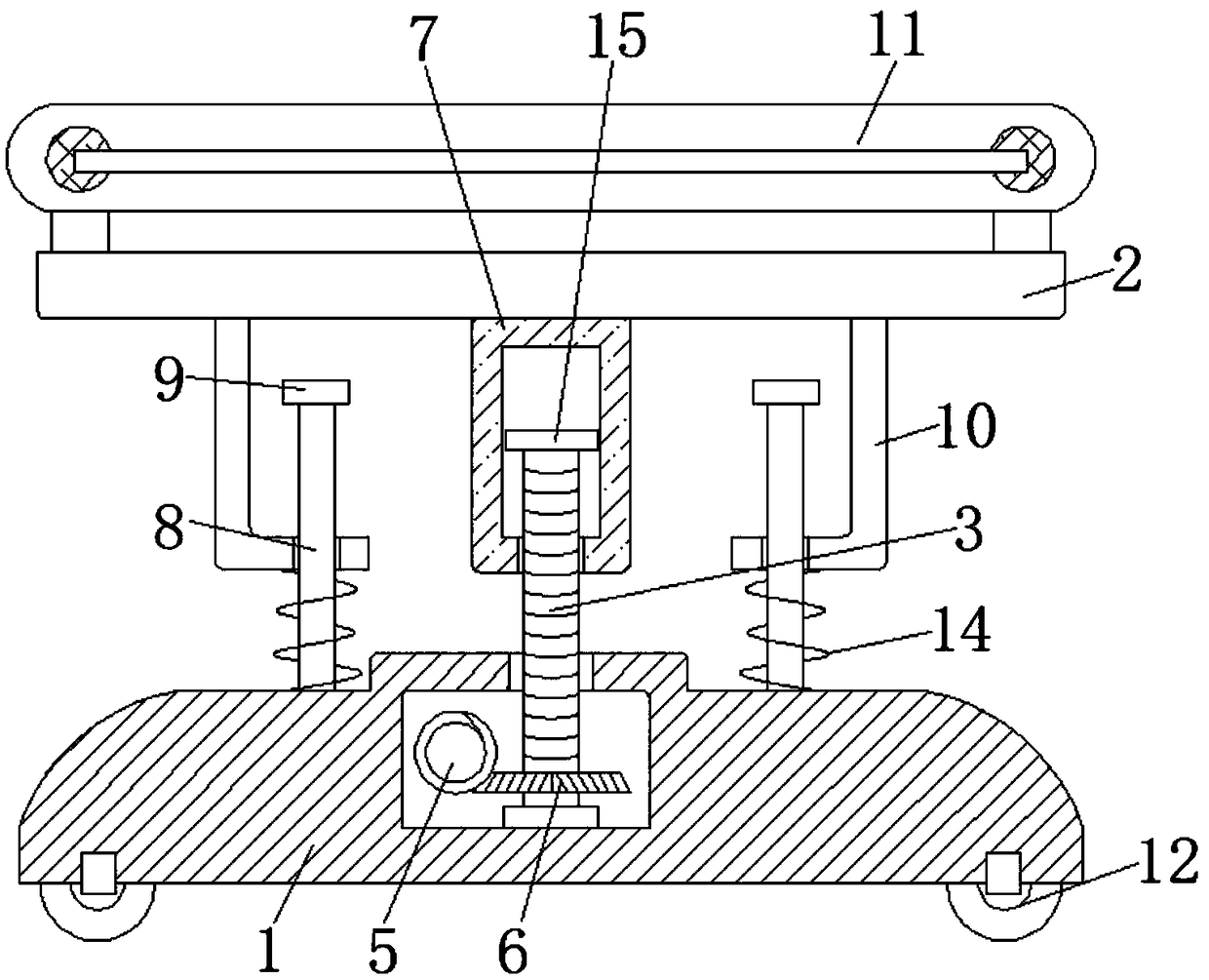
[0004] The purpose of the present invention is to solve the problem that the external mechanism of the feeding device of the automatic manipulator in the prior art is relatively simple, and the height of the device cannot be adjusted freely according to the actual use situation, and proposes a feeding device for the automatic manipulator of the CNC machine tool

Method used


Image

  • Feeding device of automatic mechanical arm of numerical control machine tool
  • Feeding device of automatic mechanical arm of numerical control machine tool

Examples


Embodiment Construction

[0016] The following will clearly and completely describe the technical solutions in the embodiments of the present invention with reference to the accompanying drawings in the embodiments of the present invention. Obviously, the described embodiments are only some, not all, embodiments of the present invention.

[0017] In describing the present invention, it should be understood that the terms "upper", "lower", "front", "rear", "left", "right", "top", "bottom", "inner", " The orientation or positional relationship indicated by "outside", etc. is based on the orientation or positional relationship shown in the drawings, and is only for the convenience of describing the present invention and simplifying the description, rather than indicating or implying that the referred device or element must have a specific orientation, so as to Specific orientation configurations and operations, therefore, are not to be construed as limitations on the invention.

[0018] refer to Figure ...


PUM


Abstract

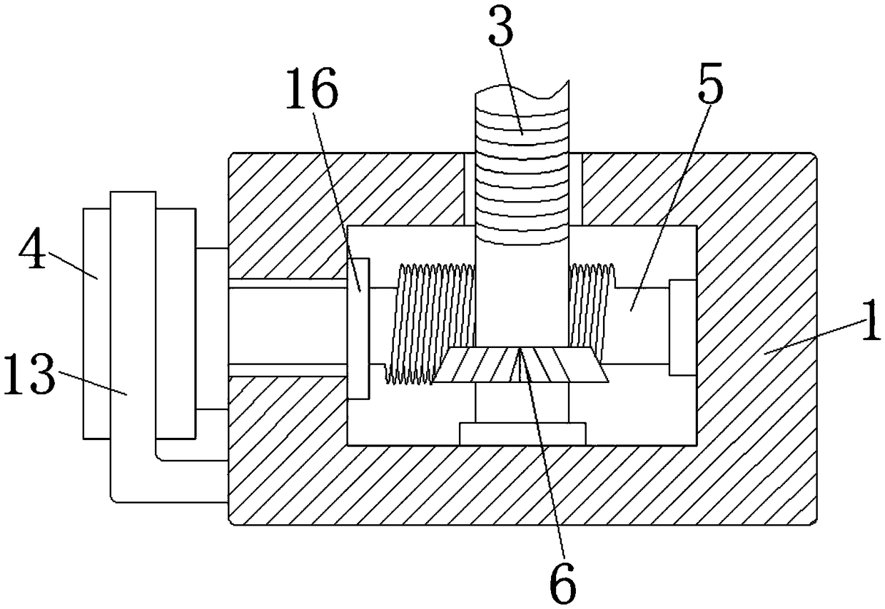
The invention discloses a feeding device of an automatic mechanical arm of a numerical control machine tool. The feeding device comprises a base and a placing plate; the placing plate is horizontallyarranged above the base, a cavity is formed in the base, a screw rod is rotatably connected into the cavity, a servo motor is fixedly connected to the outer wall of the base, the output end of the servo motor is fixedly connected with a worm, the end, away from the servo motor, of the worm penetrates through the outer wall of the base and extends into the cavity, the screw rod is fixedly sleeved with a gear engaged with the worm, one end of the screw rod penetrates through the top of the interior of the cavity and extends outwards, the extending end of the screw rod is sleeved with a thread sleeve in a thread manner, the top of the thread sleeve is fixedly connected with the bottom of the placing plate, and multiple sliding rods are fixedly connected to the top of the base. Through arrangement of multiple transmission mechanisms, the device can be freely adjusted according to actual use conditions, and the application range of the device is improved.

Description

technical field [0001] The invention relates to the technical field of automation equipment, in particular to a feeding device for an automatic manipulator of a numerically controlled machine tool. Background technique [0002] With the progress and development of society, the creation of more and more processing equipment replaces manual labor, which enables fast, accurate and efficient automatic feeding of processing equipment during processing, thereby reducing production costs and improving the accuracy of parts. Degree and reduce the scrap rate, thereby increasing the profit of the enterprise. In the process of mechanical processing, it is often necessary to use certain tooling repeatedly. For example, in the process of punching and reaming in the field of forging presses, it is necessary to repeatedly transfer tooling punches. The product is transferred once, and then it is taken out by the worker after the stamping is completed. This manual operation method consumes...

Claims


Application Information

Patent Timeline
Patent Type & Authority Applications(China)
IPC IPC(8): B21D43/00B23Q7/04B23Q7/00
CPCB21D43/00B23Q7/00B23Q7/04
Inventor 刘志成
Owner 肇庆高新区黑阳科技有限公司
Learn More