
Large plate cutting machine

A technology for cutting machines and plates, which is applied in the direction of shearing devices, metal processing equipment, manufacturing tools, etc., which can solve the problems of broken workbench, sparks, and unstable fixing of plates to be cut, so as to improve work efficiency and facilitate operation , the effect of simple structure

Inactive Publication Date: 2018-12-18
芜湖龙鳞汽车部件有限公司
View PDF4 Cites 5 Cited by
  • Summary
  • Abstract
  • Description
  • Claims
  • Application Information

AI Technical Summary

Problems solved by technology

The steel plate is transported to the cutting platform through the conveyor, and the waste tray under the grid can catch the molten iron filings and sparks generated during cutting, and the cutting of the steel plate can be measured according to the different needs of users through the scale on the frame Length: It has the advantages of simple structure, convenient use, meeting the diverse needs of users, and high processing efficiency. However, this kind of equipment still has the situation of unstable fixing of the plate to be cut and cutting sparks that will damage the workbench.

Method used


Image

  • Large plate cutting machine
  • Large plate cutting machine
  • Large plate cutting machine

Examples


Embodiment 1

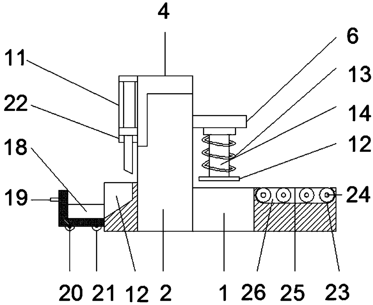
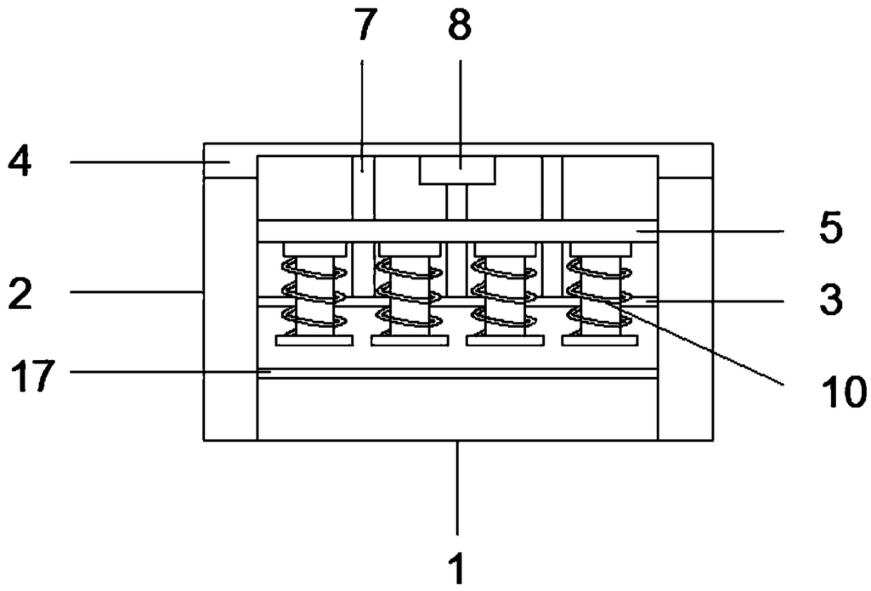
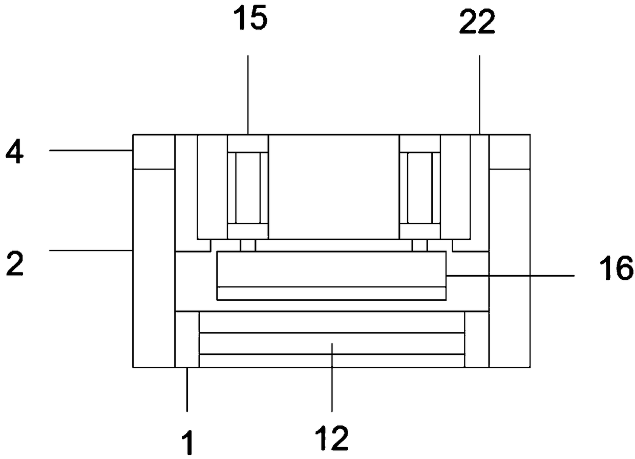
[0020] Such as Figure 1 to Figure 4 As shown, a large plate cutting machine includes a base 1, a support base 2, a support plate 3 and an upper bracket 4, the support base 2 is arranged on the side of the base 1, and the support plate 3 is fixed on the side of the support base 2 In the middle, the upper bracket 4 is fixed above the support base 2, and the support base 2 is provided with a slide rail 5, and a slide block 6 is slidably connected to the slide rail 5, and the connection between the upper bracket 4 and the support plate 3 A fixed rod 7 is fixed between them, the slider 6 is slidably connected to the fixed rod 7, a motor 8 is arranged on the upper bracket 4, and a lead screw 9 is connected to the output shaft of the motor 8, and the lead screw 9 rotates Connected to the support plate 3, the middle part of the slider 6 is provided with a threaded hole, the slider 6 is threadedly connected to the lead screw 9 through the threaded hole, the slider 6 is provided with a...

Embodiment 2

[0023] Such as figure 1 with Figure 4 As shown, a large plate cutting machine includes a base 1, a support base 2, a support plate 3 and an upper bracket 4, the support base 2 is arranged on the side of the base 1, and the support plate 3 is fixed on the side of the support base 2 In the middle, the upper bracket 4 is fixed above the support base 2, and the support base 2 is provided with a slide rail 5, and a slide block 6 is slidably connected to the slide rail 5, and the connection between the upper bracket 4 and the support plate 3 A fixed rod 7 is fixed between them, the slider 6 is slidably connected to the fixed rod 7, a motor 8 is arranged on the upper bracket 4, and a lead screw 9 is connected to the output shaft of the motor 8, and the lead screw 9 rotates Connected to the support plate 3, the middle part of the slider 6 is provided with a threaded hole, the slider 6 is threadedly connected to the lead screw 9 through the threaded hole, the slider 6 is provided wit...


PUM


Abstract

The invention discloses a large plate cutting machine, and relates to the technical field of plate cutting. The large plate cutting machine comprises a base, a support seat, a support plate and an upper bracket, wherein the support seat is arranged on the side edge of the base, the support plate is fixed on the middle of the support seat, the upper bracket is fixed on the upper portion of the support seat, sliding rails are arranged on the support seat, a sliding block are slidably connected with the sliding rails, fixing rods are fixed between the upper bracket and the support plate, the upper bracket is provided with a motor, an output shaft of the motor is connected with a screw rod which is rotatably connected to the support plate, the middle of the sliding block is provided with a threaded hole, the sliding block is connected to the screw rod through the threaded hole, compression devices are arranged on the sliding block, a cutting device is fixed on the side edge of the upper bracket, and a cutting table is arranged below the cutting devices. According to the large plate cutting machine, the structure is simple, operation is convenient, plates can be effectively fixed by arranging a clamping device, and the plates can be cut quickly by arranging the cutting device.

Description

technical field [0001] The invention relates to the technical field of plate cutting, in particular to a large plate cutting machine. Background technique [0002] When cutting different plates, different plate cutting machines are required. When cutting large plates, cutting discs are generally used for cutting. Sparks will be generated during cutting, so the working platform is easy to be damaged. After multiple constructions, the cutting will be damaged due to the working platform Make the cut sheet wrong. [0003] Chinese patent application CN201510928954.3 discloses a plate cutting machine, including a cutting platform and a cutting device, the cutting device is located directly above the cutting platform, the cutting platform includes a frame, and the frame is provided with a grid , a slide rail is provided on both sides of the grid on the frame, a scale is also provided beside the slide rail on the frame, a bracket is provided on the grid, and a waste material is pro...

Claims


Application Information

Patent Timeline
Patent Type & Authority Applications(China)
IPC IPC(8): B23D15/08B23D15/14B23D33/02B23D33/00
CPCB23D15/08B23D15/14B23D33/00B23D33/02
Inventor 胡万胜朱统坤宇宙凌静
Owner 芜湖龙鳞汽车部件有限公司
Learn More