On-line cutter condition monitoring method based on information fusion and support vector machine

A support vector machine and cutting tool technology, which is applied in the direction of manufacturing tools, measuring/indicating equipment, metal processing machinery parts, etc., can solve the problems of limited accuracy, poor monitoring stability, and the inability to effectively realize tool state monitoring, etc., to achieve Improve accuracy, improve stability, increase flexibility and monitor the effects of accuracy

Inactive Publication Date: 2018-12-18
HUAZHONG UNIV OF SCI & TECH
View PDF3 Cites 28 Cited by
  • Summary
  • Abstract
  • Description
  • Claims
  • Application Information

AI Technical Summary

Benefits of technology

This technology described in this patents allows users to collect various types of sensors from their machines during operation without having them stop working or being affected negatively affects performance. It also uses an ensemble learning approach that combines different characteristics (feature extraction) techniques such as wavelets transforms, Fourier transformation, etc., along with Support Vector Machine recognizers like Random Forests and Neural Network models to provide accurate tracking over these complex systems. By combining multiple sources of data together, advanced prediction algorithms may be developed to identify potential issues early before they become significant damage. Overall, this technology helps operators better manage and control machining operations more efficiently while maintaining high levels of precision.

Problems solved by technology

This patented describes different ways for improving the performance or lifespan of machining tools used on industries like automobiles, electronics, medical devices, etc., which require precise measurement techniques such as surface roughness (Ra) measurements with high precision over time. However, current methods often rely heavily upon manual labor-intensive inspections, leading to increased maintenance expenses due to down times caused by frequent replacements of worn parts. Therefore, it would be highly desirable if better means were developed to automatically detect when the tools become dull without human intervention.

Method used


Image

  • On-line cutter condition monitoring method based on information fusion and support vector machine
  • On-line cutter condition monitoring method based on information fusion and support vector machine
  • On-line cutter condition monitoring method based on information fusion and support vector machine

Examples


Embodiment Construction

[0031] In order to make the object, technical solution and advantages of the present invention clearer, the present invention will be further described in detail below in conjunction with the accompanying drawings and embodiments. It should be understood that the specific embodiments described here are only used to explain the present invention, not to limit the present invention. In addition, the technical features involved in the various embodiments of the present invention described below can be combined with each other as long as they do not constitute a conflict with each other.

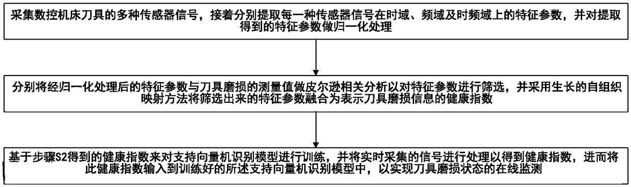
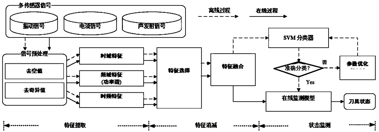
[0032] see figure 1 and figure 2 , the tool status online monitoring method based on information fusion and support vector machine provided by the present invention mainly includes the following steps:

[0033] S1, collect various sensor signals of CNC machine tools, and then extract the characteristic parameters of each sensor signal in the time domain, frequency domain and frequency domain ...


PUM


Abstract

The invention belongs to the technical field related to cutter condition monitoring of numerical control machine tools and discloses an on-line cutter condition monitoring method based on informationfusion and a support vector machine. The on-line cutter condition monitoring method comprises the following steps: S1, acquiring various sensor signals of a numerical control machine tool cutter, andextracting feature parameters of the sensor signals on a time domain, a frequency domain and a time-frequency domain; S2, performing Pearson correlation analysis on the feature parameters subjected tonormalization and a measured cutter wear value so as to screen the feature parameters, and fusing the screened feature parameters as a health index representing cutter wear information; and S3, training a support vector machine recognition model based on the obtained health index, processing a signal which is acquired in real time to obtain another health index, and inputting the obtained healthindex into the trained support vector machine recognition model to realize on-line monitoring of a cutter wear condition. The on-line cutter condition monitoring method is improved in accuracy and stability and excellent in flexibility.

Description


Claims


Application Information

Patent Timeline
Owner HUAZHONG UNIV OF SCI & TECH
Why Eureka
Try Eureka