Mechanism for sleeving valve body with O-ring

An O-ring and sleeve valve technology, which is applied to hand-held tools, manufacturing tools, etc., can solve the problems of low working efficiency of assembly equipment, and achieve the effect of improving assembly efficiency and stability.

Inactive Publication Date: 2018-12-18
苏州博鲁克机器人系统工程有限公司
View PDF0 Cites 1 Cited by
  • Summary
  • Abstract
  • Description
  • Claims
  • Application Information

AI Technical Summary

Problems solved by technology

[0002] The automatic assembly of the O-ring on the valve body requires a complete set of equipment for discharging, expanding and installing, but the existing assembly equipment for the O-ring on the valve body is relatively low in efficiency.

Method used


Image

  • Mechanism for sleeving valve body with O-ring
  • Mechanism for sleeving valve body with O-ring
  • Mechanism for sleeving valve body with O-ring

Examples


Embodiment Construction

[0014] The present invention is described in further detail now in conjunction with accompanying drawing. These drawings are all simplified schematic diagrams, which only illustrate the basic structure of the present invention in a schematic manner, so they only show the configurations related to the present invention.

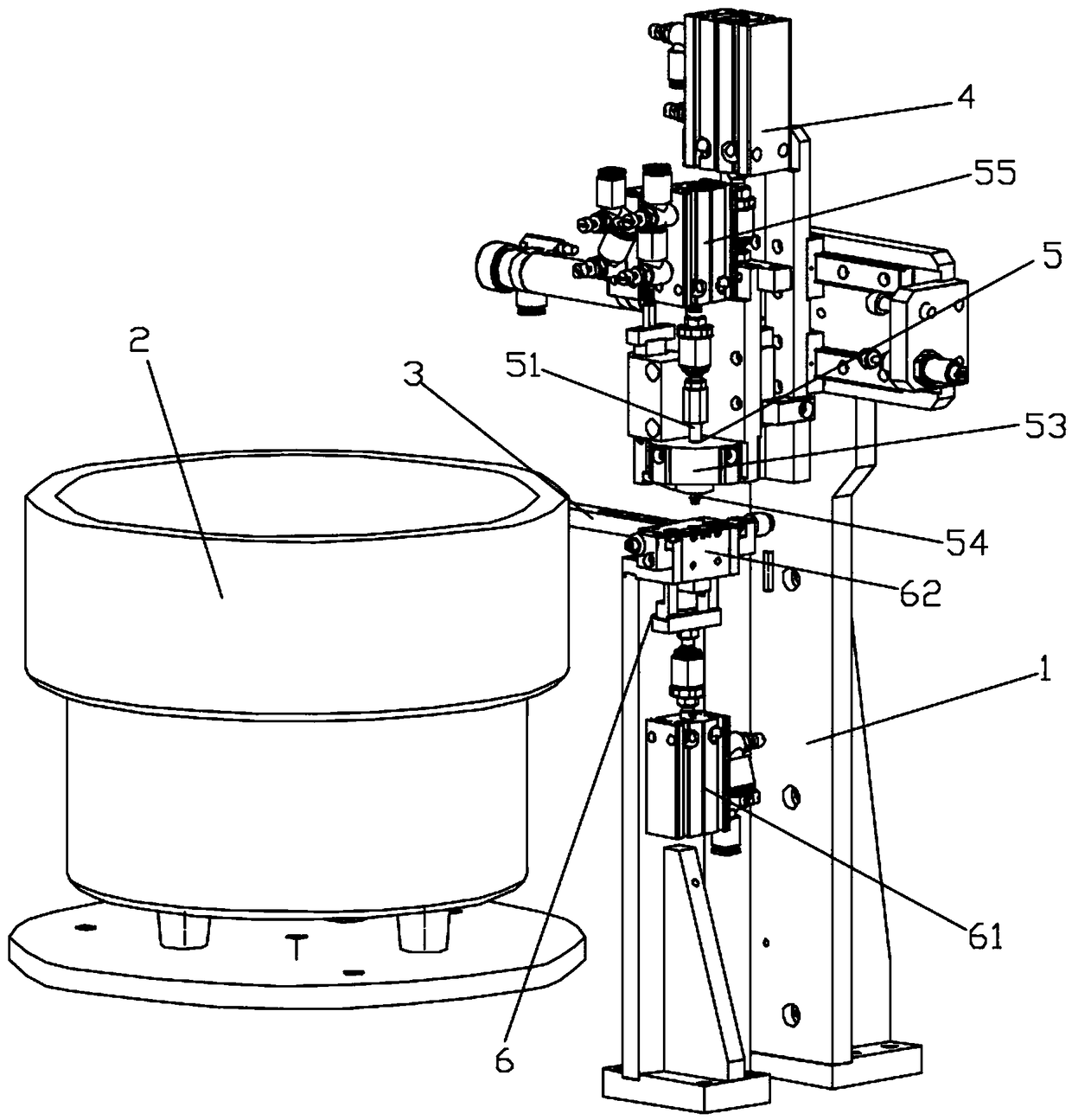
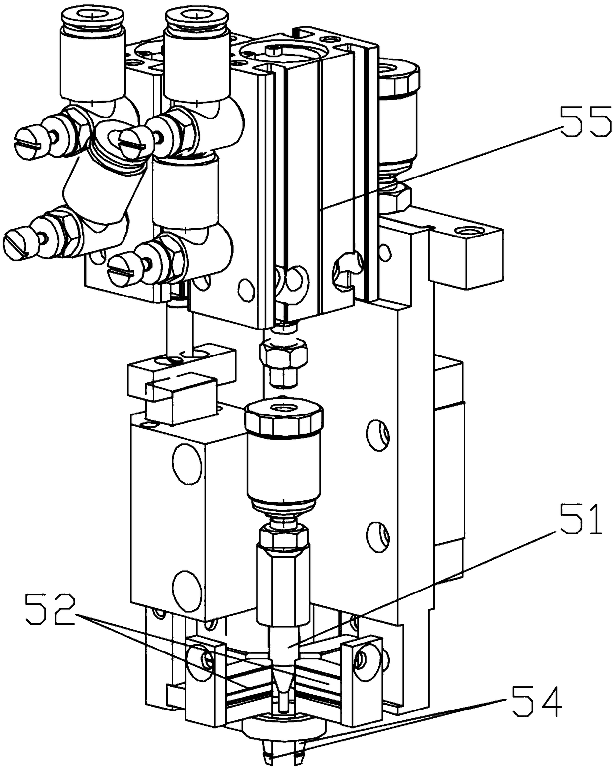
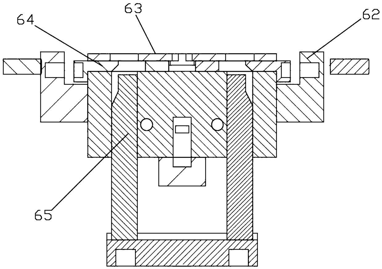
[0015] figure 1 It is a structural schematic diagram of the present invention, figure 2 It is a structural schematic diagram of the O-ring expansion mechanism of the present invention, image 3 It is a sectional view of the O-ring ejection mechanism of the present invention.

[0016] An O-ring mechanism for a sleeve valve body, including a frame 1, a vibrating plate 2, a flow channel 3, a two-axis manipulator 4, an O-ring expanding mechanism 5 and an O-ring ejecting mechanism 6, the frame 1 is A two-axis manipulator 4 and an O-ring ejection mechanism 6 are installed, the X-axis cylinder of the two-axis manipulator 4 is fixed on the frame 1, and the Y-axis ...


PUM


Abstract

The invention relates to the field of ferrule assembly mechanisms, in particular to a mechanism for sleeving a valve body with an O-ring. The mechanism comprises a frame, a vibration plate, a flow channel, a two-axis mechanical arm, an O-ring expansion mechanism and an O-ring ejection mechanism, wherein the frame is equipped with the two-axis mechanical arm and the O-ring ejection mechanism, and an X-axis cylinder of the two-axis mechanical arm is fixed on the frame, and a Y-axis moving end of the two-axis mechanical arm is fixedly provided with the O-ring expansion mechanism for picking up and expanding the O-ring, and the O-ring expansion mechanism is located at the O-ring ejection mechanism. The flow channel on the vibration plate is connected to the O-ring ejection mechanism. The invention adopts the ejection mechanism to sequentially eject the O-rings transmitted from the flow channel one by one, and cooperates with the expansion mechanism through the two-axis mechanical arm to pick the O-ring that is ejected and expand the O-ring, and then sleeves the valve body with the O-ring, thus completing the assembly, and improving the assembly efficiency and stability of the valve body and the O-ring.

Description

technical field [0001] The invention relates to the field of ring assembly mechanisms, in particular to the O-ring mechanism of a sleeve valve body. Background technique [0002] The automatic assembly of the O-ring sleeve on the valve body requires a complete set of equipment for discharging, expanding and installing, but the existing assembly equipment for the O-ring sleeve on the valve body has low working efficiency. Contents of the invention [0003] The technical problem to be solved by the present invention is: In order to solve the technical problems described in the background technology, the present invention provides a valve body O-ring mechanism, which pushes the O-rings conveyed from the flow channel one by one through the ejection mechanism. The ejected O-ring is removed and expanded through the two-axis manipulator with the expansion mechanism, and then placed on the valve body to complete the assembly, which improves the assembly efficiency and stability of...

Claims


Application Information

Patent Timeline
Patent Type & Authority Applications(China)
IPC IPC(8): B25B27/00
CPCB25B27/00
Inventor 耿宝栋
Owner 苏州博鲁克机器人系统工程有限公司
Why Eureka
Try Eureka