Automatic warning system and method of rotor vortex ring status based on aerodynamic noise monitoring

An aerodynamic noise and automatic early warning technology, applied in the field of rotorcraft, can solve problems such as the difficulty of direct monitoring of rotor tension and torque, the rotor being trapped in a deep vortex ring state, and affecting the performance of the rotor. It achieves convenient implementation, simple structure, and convenient signal acquisition. Effect

Active Publication Date: 2020-04-03
NANJING UNIV OF AERONAUTICS & ASTRONAUTICS
View PDF4 Cites 0 Cited by
  • Summary
  • Abstract
  • Description
  • Claims
  • Application Information

AI Technical Summary

Problems solved by technology

[0006] 1) It is difficult to directly monitor the rotor tension and torque. The monitoring of the rotor tension and torque requires a large number of strain gauges on the blades, which is more complicated to implement and will affect the performance of the rotor
[0007] 2) Although the rotor gradually enters the vortex ring state, it will produce a certain degree of vibration, but due to the vibration interference caused by the engine operation, it is difficult for the pilot of the helicopter or tilt rotor to find out that the rotor has entered the vortex ring earlier according to the vibration level of the cockpit. ring state, when the pilot notices a significant increase in the vibration level of the cockpit, the rotor may have been trapped in a deep vortex ring state

Method used


Image

  • Automatic warning system and method of rotor vortex ring status based on aerodynamic noise monitoring
  • Automatic warning system and method of rotor vortex ring status based on aerodynamic noise monitoring
  • Automatic warning system and method of rotor vortex ring status based on aerodynamic noise monitoring

Examples


Embodiment 1

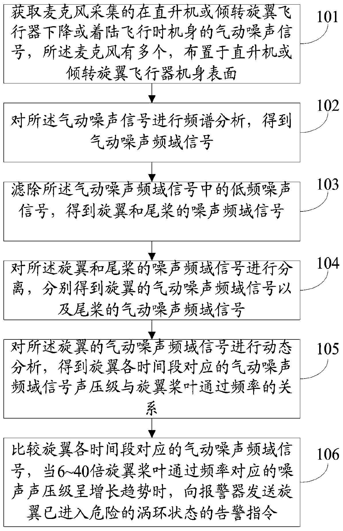
[0047] figure 1 It is a schematic flowchart of the automatic early warning method for rotor vortex ring status based on aerodynamic noise monitoring in the present invention.

[0048] Such as figure 1 As shown, the automatic warning method of rotor vortex ring status based on aerodynamic noise monitoring includes:

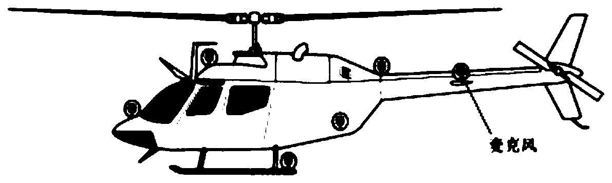
[0049] Step 101: Obtain the aerodynamic noise signal of the fuselage collected by the microphone when the helicopter or tilt-rotor aircraft descends or lands, such as image 3 As shown, there are multiple microphones arranged on the surface of the fuselage of a helicopter or a tilt-rotor aircraft;

[0050] Step 102: performing frequency spectrum analysis on the aerodynamic noise signal to obtain an aerodynamic noise frequency domain signal;

[0051] Step 103: Filter out the low-frequency noise signal in the aerodynamic noise frequency-domain signal to obtain the noise frequency-domain signal of the rotor and tail rotor;

[0052]Step 104: Separate the noise freq...

Embodiment 2

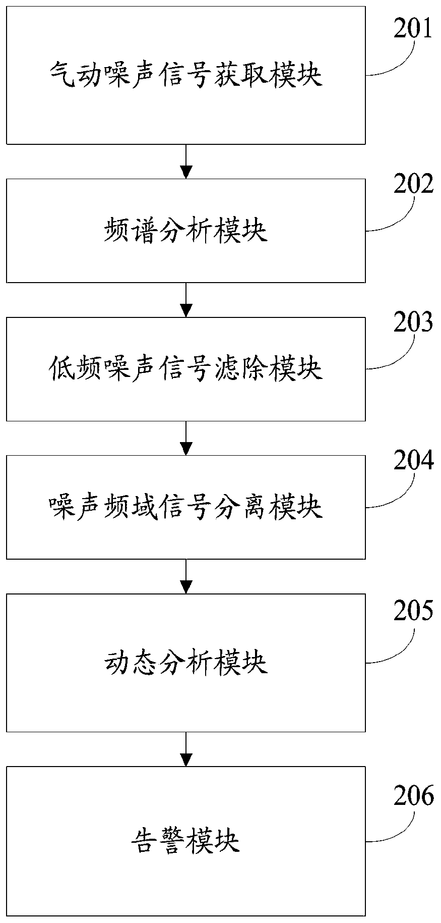
[0061] figure 2 It is a structural schematic diagram of the automatic warning system of the rotor vortex ring state based on the aerodynamic noise monitoring of the present invention.

[0062] Such as figure 2 As shown, the automatic warning system of rotor vortex ring status based on aerodynamic noise monitoring includes:

[0063] The aerodynamic noise signal acquisition module 201 is used to acquire the aerodynamic noise signal of the fuselage collected by the microphone when the helicopter or the tilt-rotor aircraft descends or lands, and there are multiple microphones arranged on the surface of the fuselage of the helicopter or the tilt-rotor aircraft ;

[0064] A spectrum analysis module 202, configured to perform spectrum analysis on the aerodynamic noise signal to obtain an aerodynamic noise frequency domain signal;

[0065] The low-frequency noise signal filtering module 203 is used to filter out the low-frequency noise signal in the aerodynamic noise frequency-do...

Embodiment 3

[0078] Taking a single-rotor helicopter with a tail rotor as an example, the number of rotor and tail rotor blades is two, the passing frequency of the rotor blade is 13Hz, and the passing frequency of the tail rotor is 55Hz. The automatic warning of the rotor vortex ring status based on aerodynamic noise monitoring Methods include:

[0079] Acquisition of aerodynamic noise signal: Acquire the aerodynamic noise signal of the fuselage collected by the microphone when the helicopter or tilt-rotor aircraft descends or lands, such as image 3 As shown, there are multiple microphones, which are arranged on the surface of the fuselage of a helicopter or a tilt-rotor aircraft. When doing other flights such as level flight, the microphones are kept closed to improve their service life.

[0080] Aerodynamic noise signal spectrum analysis: Divide the time-domain dynamic noise signal of each microphone into several segments. For example, assuming that the current noise signal has been co...


PUM


Abstract

The invention discloses a rotor vortex ring state automatic early warning method based on aerodynamic noise monitoring. The automatic warning method comprises the following steps of: acquiring aerodynamic noise signals of a fuselage during descent or landing flight collected by a microphone having a plurality of microphones arranged on a fuselage surface of a helicopter or a tilt rotor aircraft; The aerodynamic noise signal is analyzed by frequency spectrum, and the aerodynamic noise signal in frequency domain is obtained. The low frequency noise signal is filtered to obtain the noise signal of rotor and tail rotor in frequency domain and then separated. Dynamic analysis of rotor aerodynamic noise signals in frequency domain; When the noise pressure level corresponding to the rotor blade passing frequency of 6-40 times is increasing, an alarm command is sent to the rotor to alert that the rotor has entered into a dangerous vortex ring state. The invention can more conveniently realizetimely and automatic early warning when the rotor enters the vortex ring state, and ensure the safety of the helicopter and the tilt rotor aircraft when landing.

Description

technical field [0001] The invention relates to the technical field of rotorcraft, in particular to an automatic warning system and method for a rotor vortex ring state based on aerodynamic noise monitoring. Background technique [0002] Entering the Vortex Ring State (VRS) when the rotor descends vertically has a great impact on the safety of the helicopter. According to relevant statistics, from 1982 to 1997 alone, there were as many as 42 serious accidents caused by helicopters falling into a vortex ring state when landing. [0003] Severe vortex rings will also occur in tilting rotorcraft. In 2000, when a U.S. Marine Corps V-22 "Osprey" tilt-rotor aircraft landed, because one rotor was caught in a vortex ring, the fuselage rolled uncontrollably and fell rapidly, directly causing 19 occupants to die. tragedy. Therefore, it is of great practical significance to explore the early warning method of the vortex ring state to ensure the flight safety of the rotorcraft. [0...

Claims


Application Information

Patent Timeline
Patent Type & Authority Patents(China)
IPC IPC(8): B64D47/02B64D47/00B64D45/00
CPCB64D45/00B64D47/00B64D47/02
Inventor 徐国华史勇杰王亮权
Owner NANJING UNIV OF AERONAUTICS & ASTRONAUTICS
Why Eureka
Try Eureka