Smart air drying system

An intelligent and control box technology, applied in washing equipment, textiles and papermaking, household appliances, etc., can solve problems such as sore hands, slow hanging and unloading, and unmanned collection

Active Publication Date: 2018-12-18
义乌市添诚科技有限公司
9 Cites 8 Cited by

AI-Extracted Technical Summary

Problems solved by technology

[0002] Nowadays, most of the drying racks on the balcony of the building are fixed on the top of the balcony. Since the drying rack is high and has no lifting function, when hanging clothes to be dried, it is necessary to use a clothes rail for hanging. Raising your hand to hang clothes will cause sore hands, and the hanging is slow, and the existing hangers do not have intelligent temperature sensing, rain sensing and light sensing syst...

Abstract

The invention belongs to the technical field of smart home, and particularly relates to a smart airing system. The smart airing system achieves the technical purpose of having lifting, temperature sensing, rain sensing, and photosensitive sensing functions. According to the technical implementation scheme, the smart airing system comprises a control box, a control panel, a display screen, a support rod, a first motor, a lead screw, a nut, a second motor, a gear, a first sliding rail, a first sliding block, a rack and the like; the control box is installed on the wall surface of a balcony, thecontrol panel and the display screen are installed on the control box, the control box internally comprises a switching power supply, a power supply module and a control module, and the power supply module is in circuit connection with the switching power supply. The system achieves the intelligent sensing control functions through the control module, a raindrop sensor, a photosensitive sensor anda temperature sensor, when a user is not at home, aired clothes can be well collected back to the balcony, and the system is very practical and convenient to use.

Application Domain

Other drying apparatusTextiles and paper

Technology Topic

Control functionAir drying +3

Image

  • Smart air drying system
  • Smart air drying system
  • Smart air drying system

Examples

  • Experimental program(4)

Example Embodiment

[0016] Example 1
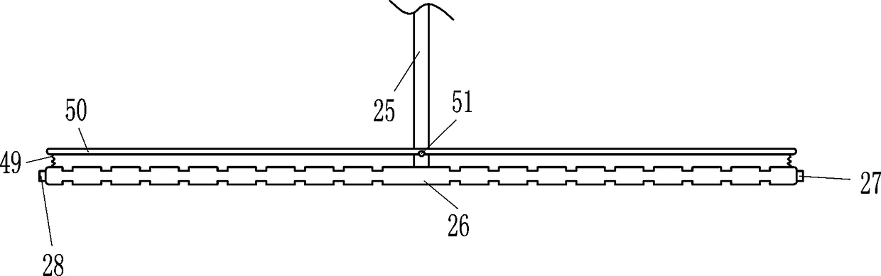
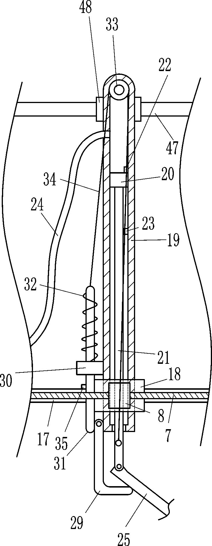
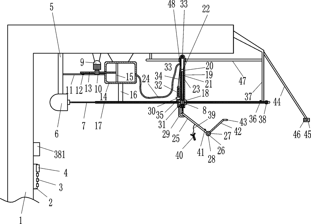
[0017] An intelligent drying system, such as Figure 1-5 As shown, it includes a control box 2, a control panel 3, a display screen 4, a pole 5, a first motor 6, a screw 7, a nut 8, a second motor 9, a gear 10, a first slide rail 11, a first slide Block 12, rack 13, wide cylinder 14, large piston 15, first connecting rod 16, guide rail 17, guide block 18, long cylinder 19, small piston 20, second connecting rod 21, first travel switch 22, Second travel switch 23, hose 24, swing lever 25, hanging rod 26, raindrop sensor 27, photosensitive sensor 28, L-shaped connecting rod 29, guide sleeve 30, plunger 31, first spring 32, pulley 33, string 34. The third travel switch 35, the fourth travel switch 36, the first connecting rod 37 and the bearing seat 38, the control box 2 is installed on the wall of the balcony 1, and the control panel 3 and the display screen 4 are installed on the control box 2, The control box 2 includes a switching power supply, a power supply module and a control module. The power supply module and the switching power supply are connected by lines. The control panel 3 includes a setting button, plus 1 button and minus 1 button. Rod 5, the first motor 6 is installed under the pole 5, the pole 5 is connected with the first motor 6 by bolt connection, the output shaft of the first motor 6 is fixedly connected with the screw rod 7, and the screw rod 7 is equipped with a nut 8. A second motor 9 is installed on the top of the balcony 1. The second motor 9 is connected to the balcony 1 through bolt connection. The second motor 9 is located on the right side of the pole 5, and the output shaft of the second motor 9 is connected with interference There is a gear 10, the right side of the pole 5 is fixedly connected with a first slide rail 11, the first slide rail 11 is slidably connected with a first slider 12, and the first slider 12 is fixedly connected with a rack 13, and the gear 10 and The rack 13 is meshed, and the right end of the rack 13 is fixedly connected with a large piston 15. A wide cylinder 14 is installed on the top of the balcony 1. The wide cylinder 14 is connected to the balcony 1 by bolts, and the large piston 15 cooperates with the wide cylinder 14. , the bottom of the wide cylinder 14 is fixedly connected with the first connecting rod 16, the bottom of the first connecting rod 16 is fixedly connected with the guide rail 17, the guide rail 17 is positioned at the rear side of the screw rod 7, and the guide rail 17 is slidably connected with a guide block 18, and the guide rail 17 is slidably connected with the guide block 18. The rear side of the block 18 is connected with a long cylinder 19, the guide block 18 is connected with the long cylinder 19 by welding, the guide block 18 is fixedly connected with the nut 8, the long cylinder 19 is equipped with a small piston 20, and the bottom of the small piston 20 Fixedly connected with the second connecting rod 21, the first stroke switch 22 is installed on the upper right wall in the long cylinder body 19, the second stroke switch 23 is installed on the middle part of the right wall in the long cylinder body 19, and the flexible pipe 24 one end is connected with the wide cylinder body 14 The right wall of the hose 24 communicates with the upper left wall of the long cylinder body 19. The lower end of the second connecting rod 21 slides through the long cylinder body 19 and is hinged with a swing rod 25. The other end of the swing rod 25 is fixedly connected with a Hanging rod 26, raindrop sensor 27 and photosensitive sensor 28 are respectively installed at the front and rear ends of hanging rod 26, the left side of long cylinder body 19 is rotatably connected with L-shaped connecting rod 29, and the left side of long cylinder body 19 is fixedly connected with guide sleeve 30, The guide sleeve 30 is located above the L-shaped connecting rod 29, and the guide sleeve 30 is slidably connected with an insertion rod 31. The first spring 32 is located above the guide sleeve 30 and is enclosed within the insertion rod 31. The first spring 32 lower ends are affixed to the guide sleeve 30, the first spring 32 upper ends are affixed to the insertion rod 31, the insertion rod 31 upper end is tied with a string 34, and the front side of the long cylinder body 19 is rotatably connected to a pulley 33, and the string 34 goes around The pulley 33 is connected to the bottom of the second connecting rod 21, and the third travel switch 35 and the fourth travel switch 36 are installed above the guide rail 17. There is a first connecting rod 37, the first connecting rod 37 is fixedly connected with the guide rail 17, the first connecting rod 37 is connected with the guide rail 17 by welding, the right front side of the guide rail 17 is equipped with a bearing seat 38, and the screw mandrel 7 is connected to the In the bearing seat 38, an alarm device 381 is installed on the upper left part of the inner side of the balcony 1, setting key, plus 1 key, minus 1 key, power module, display screen 4, first motor 6, second motor 9, raindrop sensor 27, photosensitive The sensor 28, the first travel switch 22, the second travel switch 23, the third travel switch 35, the fourth travel switch 36 and the alarm device 381 are all connected to the control module through lines.

Example Embodiment

[0018] Example 2
[0019] An intelligent drying system, such as Figure 1-5 As shown, it includes a control box 2, a control panel 3, a display screen 4, a pole 5, a first motor 6, a screw 7, a nut 8, a second motor 9, a gear 10, a first slide rail 11, a first slide Block 12, rack 13, wide cylinder 14, large piston 15, first connecting rod 16, guide rail 17, guide block 18, long cylinder 19, small piston 20, second connecting rod 21, first travel switch 22, Second travel switch 23, hose 24, swing lever 25, hanging rod 26, raindrop sensor 27, photosensitive sensor 28, L-shaped connecting rod 29, guide sleeve 30, plunger 31, first spring 32, pulley 33, string 34. The third travel switch 35, the fourth travel switch 36, the first connecting rod 37 and the bearing seat 38, the control box 2 is installed on the wall of the balcony 1, and the control panel 3 and the display screen 4 are installed on the control box 2, The control box 2 includes a switching power supply, a power supply module and a control module. The power supply module and the switching power supply are connected by lines. The control panel 3 includes a setting button, plus 1 button and minus 1 button. Rod 5, a first motor 6 is installed below the pole 5, the output shaft of the first motor 6 is fixedly connected with the screw mandrel 7, and the screw mandrel 7 is equipped with a nut 8, and the second motor 9 is installed on the top of the balcony 1, and the second The motor 9 is located on the right side of the pole 5, the output shaft of the second motor 9 is interference-connected with a gear 10, the right side of the pole 5 is fixedly connected with a first slide rail 11, and the first slide rail 11 is slidably connected with a second A slider 12, the first slider 12 is fixedly connected with a rack 13, the gear 10 meshes with the rack 13, the right end of the rack 13 is fixedly connected with a large piston 15, and the inner top of the balcony 1 is equipped with a wide cylinder 14, a large piston 15 cooperates with the wide cylinder body 14, the bottom of the wide cylinder body 14 is fixedly connected with the first connecting rod 16, the bottom of the first connecting rod 16 is fixedly connected with the guide rail 17, the guide rail 17 is located at the rear side of the screw rod 7, and the slide type on the guide rail 17 A guide block 18 is connected, and a long cylinder body 19 is connected to the rear side of the guide block 18. The guide block 18 is fixedly connected to the nut 8. A small piston 20 is fitted in the long cylinder body 19, and a second connecting rod 21 is fixedly connected below the small piston 20. , a first stroke switch 22 is installed on the top of the inner right wall of the long cylinder body 19, a second stroke switch 23 is installed on the middle part of the right wall in the long cylinder body 19, and one end of the hose 24 communicates with the right wall of the wide cylinder body 14, and the hose 24 The other end communicates with the left wall top of the long cylinder body 19. The lower end of the second connecting rod 21 slides through the long cylinder body 19 and is hinged with a swing rod 25. The other end of the swing rod 25 is fixedly connected with a hanging rod 26. A raindrop sensor 27 and a photosensitive sensor 28 are respectively installed at both ends. The left side of the long cylinder body 19 is rotatably connected with an L-shaped connecting rod 29. 29, the guide sleeve 30 is slidably connected with the insertion rod 31, the first spring 32 is located above the guide sleeve 30 and is set on the insertion rod 31, the lower end of the first spring 32 is fixedly connected with the guide sleeve 30, and the upper end of the first spring 32 Fixedly connected with the insertion rod 31, the upper end of the insertion rod 31 is tied with a string 34, and the front side of the long cylinder body 19 is rotatably connected with a pulley 33. The third travel switch 35 and the fourth travel switch 36 are installed above the rail 17, the third travel switch 35 is positioned at the left side of the fourth travel switch 36, the first connecting rod 37 is installed on the right side of the balcony 1, and the first connecting rod 37 is fixedly connected with guide rail 17, bearing seat 38 is installed on the right front side of guide rail 17, screw mandrel 7 is interference-connected in bearing seat 38, and alarm device 381 is installed on balcony 1 inner side upper left part, setting key, plus 1 key, minus 1 Key, power module, display screen 4, first motor 6, second motor 9, raindrop sensor 27, photosensitive sensor 28, first travel switch 22, second travel switch 23, third travel switch 35, fourth travel switch 36 and alarm device 381 are all connected with the control module by lines.
[0020] Also include backguy 39, clamp 40 and temperature sensor 41, temperature sensor 41 is installed on the swing bar 25, swing bar 25 is connected with temperature sensor 41 by the mode of bolt connection, is connected with backguy 39 below the swing bar 25, and the other end of backguy 39 A clip 40 is connected, and the temperature sensor 41 is connected with the control module through a line.

Example Embodiment

[0021] Example 3
[0022] An intelligent drying system, such as Figure 1-5 As shown, it includes a control box 2, a control panel 3, a display screen 4, a pole 5, a first motor 6, a screw 7, a nut 8, a second motor 9, a gear 10, a first slide rail 11, a first slide Block 12, rack 13, wide cylinder 14, large piston 15, first connecting rod 16, guide rail 17, guide block 18, long cylinder 19, small piston 20, second connecting rod 21, first travel switch 22, Second travel switch 23, hose 24, swing lever 25, hanging rod 26, raindrop sensor 27, photosensitive sensor 28, L-shaped connecting rod 29, guide sleeve 30, plunger 31, first spring 32, pulley 33, string 34. The third travel switch 35, the fourth travel switch 36, the first connecting rod 37 and the bearing seat 38, the control box 2 is installed on the wall of the balcony 1, and the control panel 3 and the display screen 4 are installed on the control box 2, The control box 2 includes a switching power supply, a power supply module and a control module. The power supply module and the switching power supply are connected by lines. The control panel 3 includes a setting button, plus 1 button and minus 1 button. Rod 5, a first motor 6 is installed below the pole 5, the output shaft of the first motor 6 is fixedly connected with the screw mandrel 7, and the screw mandrel 7 is equipped with a nut 8, and the second motor 9 is installed on the top of the balcony 1, and the second The motor 9 is located on the right side of the pole 5, the output shaft of the second motor 9 is interference-connected with a gear 10, the right side of the pole 5 is fixedly connected with a first slide rail 11, and the first slide rail 11 is slidably connected with a second A slider 12, the first slider 12 is fixedly connected with a rack 13, the gear 10 meshes with the rack 13, the right end of the rack 13 is fixedly connected with a large piston 15, and the inner top of the balcony 1 is equipped with a wide cylinder 14, a large piston 15 cooperates with the wide cylinder body 14, the bottom of the wide cylinder body 14 is fixedly connected with the first connecting rod 16, the bottom of the first connecting rod 16 is fixedly connected with the guide rail 17, the guide rail 17 is located at the rear side of the screw rod 7, and the slide type on the guide rail 17 A guide block 18 is connected, and a long cylinder body 19 is connected to the rear side of the guide block 18. The guide block 18 is fixedly connected to the nut 8. A small piston 20 is fitted in the long cylinder body 19, and a second connecting rod 21 is fixedly connected below the small piston 20. , a first stroke switch 22 is installed on the top of the inner right wall of the long cylinder body 19, a second stroke switch 23 is installed on the middle part of the right wall in the long cylinder body 19, and one end of the hose 24 communicates with the right wall of the wide cylinder body 14, and the hose 24 The other end communicates with the left wall top of the long cylinder body 19. The lower end of the second connecting rod 21 slides through the long cylinder body 19 and is hinged with a swing rod 25. The other end of the swing rod 25 is fixedly connected with a hanging rod 26. A raindrop sensor 27 and a photosensitive sensor 28 are respectively installed at both ends. The left side of the long cylinder body 19 is rotatably connected with an L-shaped connecting rod 29. 29, the guide sleeve 30 is slidably connected with the insertion rod 31, the first spring 32 is located above the guide sleeve 30 and is set on the insertion rod 31, the lower end of the first spring 32 is fixedly connected with the guide sleeve 30, and the upper end of the first spring 32 Fixedly connected with the insertion rod 31, the upper end of the insertion rod 31 is tied with a string 34, and the front side of the long cylinder body 19 is rotatably connected with a pulley 33. The third travel switch 35 and the fourth travel switch 36 are installed above the rail 17, the third travel switch 35 is positioned at the left side of the fourth travel switch 36, the first connecting rod 37 is installed on the right side of the balcony 1, and the first connecting rod 37 is fixedly connected with guide rail 17, bearing seat 38 is installed on the right front side of guide rail 17, screw mandrel 7 is interference-connected in bearing seat 38, and alarm device 381 is installed on balcony 1 inner side upper left part, setting key, plus 1 key, minus 1 Key, power module, display screen 4, first motor 6, second motor 9, raindrop sensor 27, photosensitive sensor 28, first travel switch 22, second travel switch 23, third travel switch 35, fourth travel switch 36 and alarm device 381 are all connected with the control module by lines.
[0023] Also includes backguy 39, clip 40 and temperature sensor 41, temperature sensor 41 is installed on the swing bar 25, is connected with backguy 39 below the swing bar 25, and the other end of backguy 39 is connected with clip 40, and temperature sensor 41 and control module are connected by line .
[0024] Also include the second connecting rod 42, the first electromagnet 43, the third connecting rod 44 and the second electromagnet 45, the right side of the hanging rod 26 is fixedly connected with the second connecting rod 42, and the hanging rod 26 is connected with the connecting rod by welding. The second connecting rod 42 is connected, and the first electromagnet 43 is installed on the other end of the second connecting rod 42, and the third connecting rod 44 is fixedly connected to the right side of the first connecting rod 37, and the first connecting rod 37 is connected with the first connecting rod 37 by welding. Three connecting rods 44 are connected, and the second electromagnet 45 is installed on the lower end of the third connecting rod 44, and the second electromagnet 45 has a groove 46, and the first electromagnet 43 cooperates with the groove 46 on the second electromagnet 45, Both the first electromagnet 43 and the second electromagnet 45 are connected with the control module through lines.

PUM

no PUM

Description & Claims & Application Information

We can also present the details of the Description, Claims and Application information to help users get a comprehensive understanding of the technical details of the patent, such as background art, summary of invention, brief description of drawings, description of embodiments, and other original content. On the other hand, users can also determine the specific scope of protection of the technology through the list of claims; as well as understand the changes in the life cycle of the technology with the presentation of the patent timeline. Login to view more.
Why Eureka
Try Eureka