Medical equipment cooling fan

A cooling fan and medical equipment technology, applied in mechanical equipment, machine/engine, pump control, etc., can solve problems such as failure to detect fan problems in time, loud fan rotation noise, poor motor feedback accuracy, etc., to facilitate intelligent control, The effect of reducing motor noise and wind noise and avoiding damage

Inactive Publication Date: 2018-12-18
ANHUI AIKEER PHARMA CO LTD
View PDF5 Cites 1 Cited by
  • Summary
  • Abstract
  • Description
  • Claims
  • Application Information

AI Technical Summary

Problems solved by technology

[0002] China's medical equipment industry has grown from small to large, and has a considerable scale, and has maintained a rapid growth rate. According to the data of the National Bureau of Statistics, by the end of 2014, China's medical equipment industry reached 420 billion yuan, with an annual growth rate of 15%. , which is much higher than the annual growth rate of the international medical equipment industry of 7%. In the global market, the proportion of medical equipment and pharmaceutical consumption is about 1:1, and the proportion of medical equipment in developed countries is even higher, while the proportion of medical equipment and pharmaceutical expenses in China is about It is 0.32:1, which is much lower than the international average level. Therefore, there is still a large gap in China's medical equipment industry, and there is still a large market space for the medical equipment industry. Since medical equipment is a high-end precision equipment, the internal structure is complex and there are many circuit components. Therefore, higher requirements are put forward for the heat dissipation of medical mechanical equipment. At present, the commonly used cooling fan motors for medical equipment have low cooling efficiency, large fan rotation noise, and vibration problems during fan rotation. In addition, the feedback accuracy of the motor is poor and cannot be detected in time. Fan problem, so the structure of the fan motor needs to be modified

Method used


Image

  • Medical equipment cooling fan

Examples


Embodiment Construction

[0018] The following will clearly and completely describe the technical solutions in the embodiments of the present invention with reference to the accompanying drawings in the embodiments of the present invention. Obviously, the described embodiments are only some, not all, embodiments of the present invention. All other embodiments obtained by persons of ordinary skill in the art based on the embodiments of the present invention belong to the protection scope of the present invention.

[0019] According to an embodiment of the present invention, a cooling fan for medical equipment is provided.

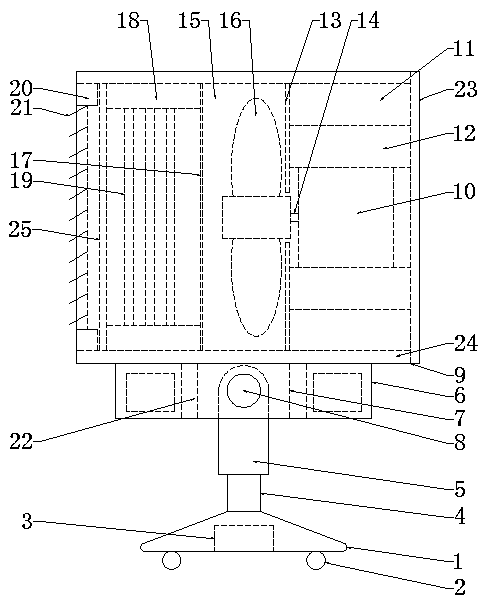
[0020] Such as figure 1 As shown, a cooling fan for medical equipment according to an embodiment of the present invention includes a support base 1, a plurality of rollers 2 are provided on the bottom of the support base 1, and a driving motor 3 is provided inside the support base 1. The driving motor one 3 is connected with the transmission of the roller 2, the top of the support s...


PUM


Abstract

The invention discloses a medical equipment cooling fan. The medical equipment cooling fan comprises a supporting seat, a plurality of rolling wheels are arranged at the bottom of the supporting seat,a first driving motor is arranged in the supporting seat and in transmission connection with the rolling wheels, a supporting rod is arranged at the top of the supporting seat, a jacking device is arranged at the top of the supporting rod, the upper part of the supporting rod extends to the interior of the jacking device, and a mounting seat is arranged at the top of the jacking device; and a second driving motor is arranged in the mounting seat, a first rotating shaft is arranged on the second driving motor, the jacking device is fixedly connected with the second driving motor through the first rotating shaft, a fixing sleeve is arranged at the top of the mounting seat, a third driving motor is arranged on one side of the interior of the fixing sleeve, a sound isolation sleeve is arranged between the third driving motor and the inner wall of the fixing sleeve, a plurality of cooling pieces are arranged between the sound isolation sleeve and the third driving motor, and a filtering screen is arranged at the end, close to the inner side of the fixing sleeve, of the third driving motor. The medical equipment cooling fan has the beneficial effects of being convenient to connect and obvious in cooling effect.

Description

technical field [0001] The invention relates to the field of medical equipment, in particular to a cooling fan for medical equipment. Background technique [0002] China's medical equipment industry has grown from small to large, and has a considerable scale, and has maintained a relatively rapid growth rate. According to the data of the National Bureau of Statistics, by the end of 2014, China's medical equipment industry had reached 420 billion yuan, with an annual growth rate of 15%. , far higher than the annual growth rate of the international medical equipment industry of 7%. In the global market, the proportion of medical equipment and pharmaceutical consumption is about 1:1, and the proportion of medical equipment in developed countries is even higher, while the proportion of medical equipment and pharmaceutical expenses in China is about It is 0.32:1, which is much lower than the international average level. Therefore, there is still a large gap in China's medical e...

Claims


Application Information

Patent Timeline
IPC IPC(8): F04D25/08F04D25/06F04D29/58F04D29/66F04D29/70F04D29/00F04D27/00
CPCF04D25/06F04D25/08F04D27/00F04D29/002F04D29/582F04D29/664F04D29/703
Inventor 王殿阔
Owner ANHUI AIKEER PHARMA CO LTD
Why Eureka
Try Eureka