Brake pad and vehicle

A technology of brake pads and brake discs, which is applied in the field of vehicle engineering, can solve problems such as poor heat dissipation, and achieve the effects of improving heat dissipation performance, reducing wind resistance, and increasing heat dissipation area

Active Publication Date: 2018-12-18
BEIJING YINGCHUANG HUIZHI TECH
View PDF11 Cites 4 Cited by
  • Summary
  • Abstract
  • Description
  • Claims
  • Application Information

AI Technical Summary

Problems solved by technology

[0005] The purpose of the present invention is to provide a brake pad and a vehicle to sol

Method used


Image

  • Brake pad and vehicle
  • Brake pad and vehicle
  • Brake pad and vehicle

Examples


Example Embodiment

[0030] Example one

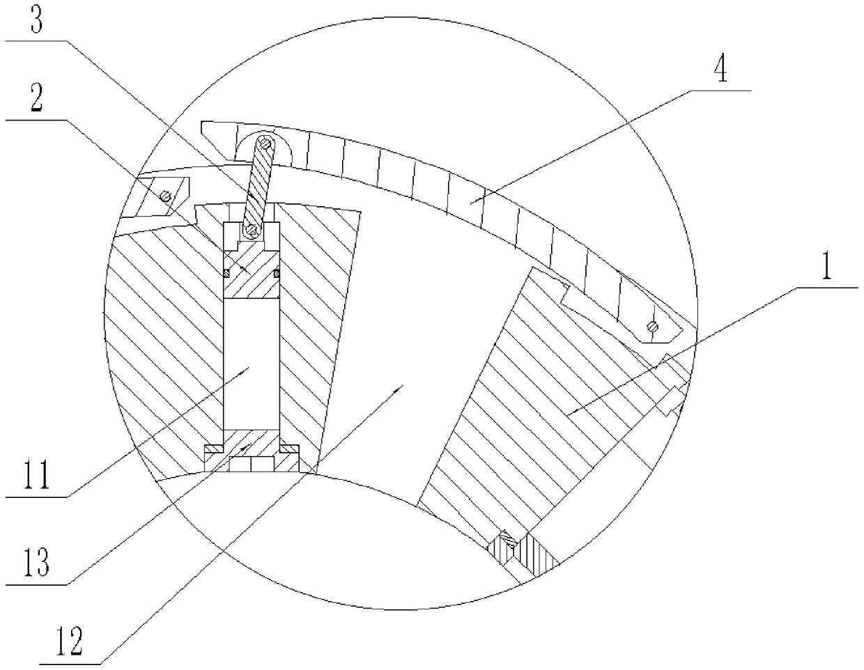
[0031] Such as figure 1 As shown, the brake pad provided by the embodiment of the present invention includes: a brake disc 1, a piston 2, a connecting rod 3, and a wind deflector 4. The wind deflector 4 is hinged on the outer peripheral surface of the brake disc 1, and the brake disc 1 The outer peripheral surface is provided with a piston hole 11, the piston 2 is inserted into the piston hole 11, one end of the connecting rod 3 is hinged with the piston 2, and the other end of the connecting rod 3 is hinged with the wind deflector 4.

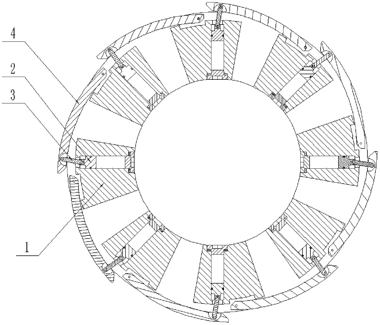
[0032] Such as figure 2 As shown, a closed space is formed between the piston 2 and the piston hole 11. During the braking process, the hydraulic caliper and the brake disc 1 friction and heat, so that the gas in the closed space between the piston 2 and the piston hole 11 is heated and expanded. The pressure in the hole 11 increases, pushing the piston 2 to slide along the piston hole 11 to the end away from the axis of the br...

Example Embodiment

[0047] Example two

[0048] The vehicle provided by the embodiment of the present invention includes the brake pad provided in the first embodiment. Since the technical effect of the vehicle provided in this embodiment is the same as the technical effect of the brake pad provided in the first embodiment, it will not be repeated here.


PUM


Abstract

The invention provides a brake pad and a vehicle, and relates to the technical field of vehicle engineering. The brake pad comprises a brake disc, a piston, a connecting rod and a wind shield. The wind shield is hinged to the periphery face of the brake disc, a piston hole is formed in the periphery face of the brake disc, the piston is inserted into the piston hole in a fit manner, one end of theconnecting rod is hinged to the piston, and the other end of the connecting rod is hinged to the wind shield. According to the brake pad, the technical problem that a traditional brake pad is poor incooling during braking, and during normal running, wind resistance is large is solved, when the brake disc is heated, the cooling area is increased, the cooling efficiency is improved, when brake isfinished, the wind resistance of the brake disc can be reduced, unnecessary energy consumption can be reduced, and the vehicle endurance mileage can be improved.

Description

technical field [0001] The invention relates to the technical field of vehicle engineering, in particular to a brake pad and a vehicle. Background technique [0002] The current brake pads mainly have two forms, one is a solid ring structure, and the other is opening holes on the inside and outside of the ring structure to increase the heat dissipation area, and the heat dissipation effect is greatly improved compared with the disc structure. [0003] When the vehicle brakes, the temperature of the brake pads rises sharply, and the friction coefficient of the brake pads decreases, resulting in weakened braking force. After the temperature rises to a certain extent, the braking effect will decrease or even fail. Brake failure is extremely dangerous, so ensuring the heat dissipation of brake pads is a key issue in the design and production of brake pads. [0004] The solid ring structure brake pad has a small heat dissipation area, poor heat dissipation effect, and the brakin...

Claims


Application Information

Patent Timeline
IPC IPC(8): F16D65/12F16D65/847
CPCF16D65/121F16D65/128F16D2065/1304F16D2065/1328
Inventor 方继根王西峰吴进军高祥汪晓光刘晓华
Owner BEIJING YINGCHUANG HUIZHI TECH
Why Eureka
Try Eureka