Oil slinger and splash lubrication structure applied to gear boxes

A technology of splash lubrication and oil throwing ring, which is applied in the field of oil throwing ring and splash lubrication structure, can solve the problems of low lubrication efficiency, achieve the effects of reducing oil stirring heat, improving lubrication efficiency and transmission efficiency, and reducing oil stirring loss

Pending Publication Date: 2018-12-18
CHONGQING GEARBOX
View PDF0 Cites 1 Cited by
  • Summary
  • Abstract
  • Description
  • Claims
  • Application Information

AI Technical Summary

Problems solved by technology

[0004] The purpose of the present invention is to provide an oil throwing ring and splash lubricating structure for a gearbox in view of the problem that the current gearbox lubrication mainly depends on the size of the oil throwing ring to improve the lubrication efficiency, but the lubrication efficiency is low in a compact gearbox

Method used


Image

  • Oil slinger and splash lubrication structure applied to gear boxes
  • Oil slinger and splash lubrication structure applied to gear boxes
  • Oil slinger and splash lubrication structure applied to gear boxes

Examples


Embodiment Construction

[0027] Below in conjunction with accompanying drawing, the present invention is described in detail.

[0028] In order to make the object, technical solution and advantages of the present invention more clear, the present invention will be further described in detail below in conjunction with the accompanying drawings and embodiments. It should be understood that the specific embodiments described here are only used to explain the present invention, not to limit the present invention.

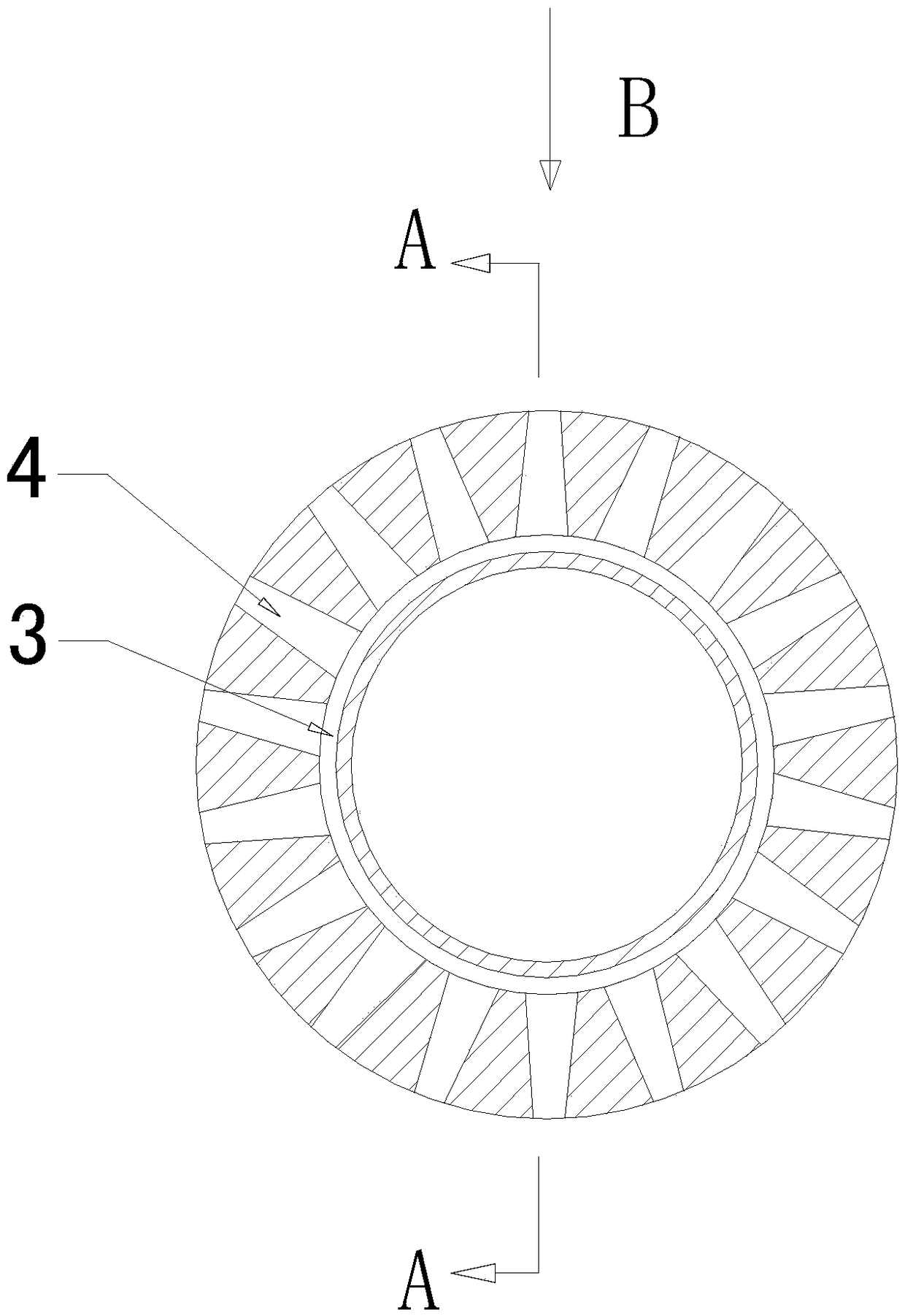
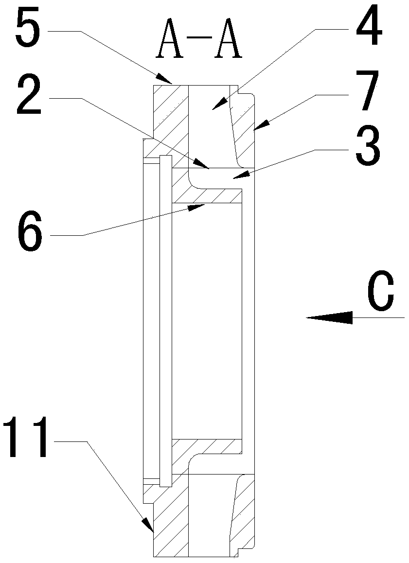
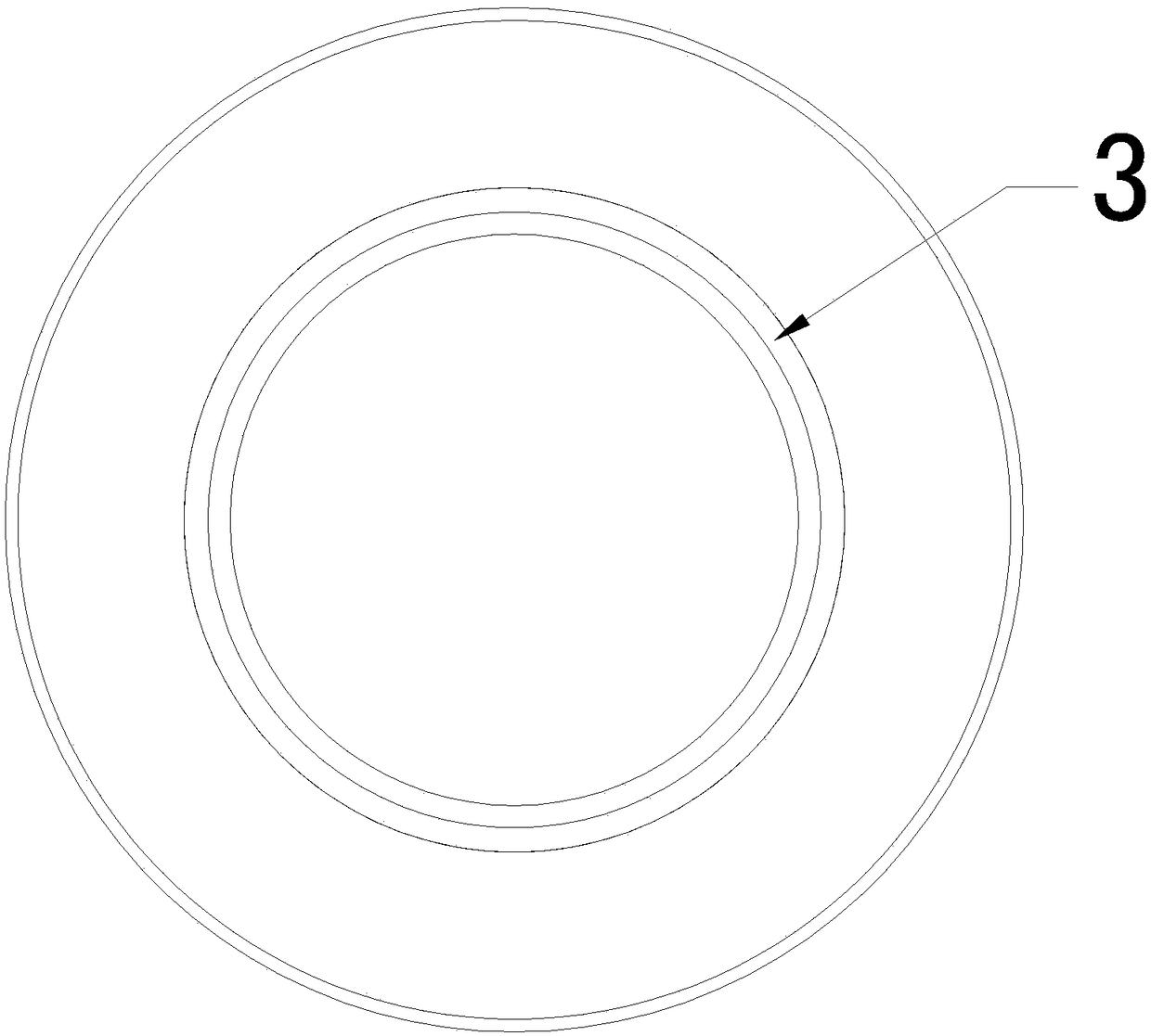
[0029] like Figure 1 ~ Figure 4 As shown, an oil throwing ring of a gear box is provided with an oil passage 2 on the oil throwing ring 1, an opening on the oil passage 2 is arranged on the outer ring surface 5 of the oil throwing ring 1, and another opening of the oil passage 2 It is arranged on the first side 7 of the oil throwing ring 1, and the first side 7 of the oil throwing ring 1 is provided with a ring groove 3, and the outer ring surface 5 of the oil throwing ring 1 is provided with...


PUM


Abstract

The invention relates to the field of gear box lubrication structures and particularly relates to an oil slinger and a splash lubrication structure applied to gear boxes. The oil slinger applied to gear boxes is provided with an oil channel; one opening of the oil channel is formed in an outer ring surface of the oil slinger; the other opening of the oil channel is formed in the first side of theoil slinger; a ring-shaped groove is formed in the first side of the oil slinger; radial holes are formed in the outer ring surface of the oil slinger and are communicated with the outer ring surfaceand the ring-shaped groove of the oil slinger; the radial holes and the ring-shaped groove form the oil channel; an opening communicated with one end of the ring-shaped groove of each radial hole is larger than an opening in one end of the outer ring surface of each radial hole. The splash lubrication structure applied to the gear boxes comprises the oil slinger and a lubrication pipeline; the oilslung out by the oil slinger enters the lubrication pipeline again; a spraying section of the lubrication pipeline is aligned to a lubricated part, so that the lubrication effect is achieved. The oilslinger and the splash lubrication structure are applied to the gear boxes with compact structure and high lubrication requirements, so that the lubrication efficiency is improved.

Description

technical field [0001] The invention relates to the field of gearbox lubricating structures, in particular to an oil throwing ring and a splash lubricating structure of a gearbox. Background technique [0002] The lubrication system of the gearbox has the functions of lubrication, cooling, cleaning, rust prevention, sealing and hydraulic pressure. Among the gears and bearings involved in the transmission, the gearbox needs to send relative sliding or movement during operation, so friction and wear will occur, which will increase power consumption and reduce transmission efficiency; especially for high-speed transmission, it is even more necessary to consider the lubrication of the gearbox. The quality of its lubrication system will affect the thermal balance of the entire gearbox and the wear of gears and bearings; in severe cases, it will also lead to broken teeth of gears, overheating or burning of bearings, which directly determine the quality and service life of the gear...

Claims


Application Information

Patent Timeline
Patent Type & Authority Applications(China)
IPC IPC(8): F16H57/04
CPCF16H57/042
Inventor 王猛张立婷高德芳孙继成冉贞德
Owner CHONGQING GEARBOX
Why Eureka
Try Eureka