Efficient energy saving pump

A high-efficiency energy-saving, pump body technology, applied in the direction of pumps, pump devices, liquid variable capacity machinery, etc., can solve the problems of energy loss of liquid media, difficulty in generating multiple flow rates, and speed vector differences, and achieve the goal of reducing energy loss Effect

Pending Publication Date: 2018-12-07
台州市禺工泵业科技有限公司
View PDF14 Cites 0 Cited by
  • Summary
  • Abstract
  • Description
  • Claims
  • Application Information

AI Technical Summary

Problems solved by technology

Generally, jet pump impeller pressurized water discharge is radial, which is different from nozzle axial water discharge, which leads to a large loss of liquid medium energy
At the same time, due to the difference in the inlet of the two parts of the mixed liquid medium, the difference in the velocity vector causes a considerable pa...

Method used


Image

  • Efficient energy saving pump
  • Efficient energy saving pump
  • Efficient energy saving pump

Examples


Embodiment Construction

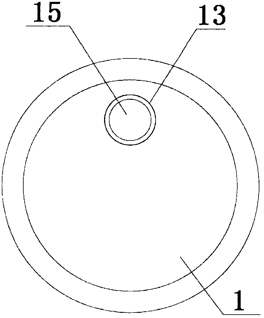
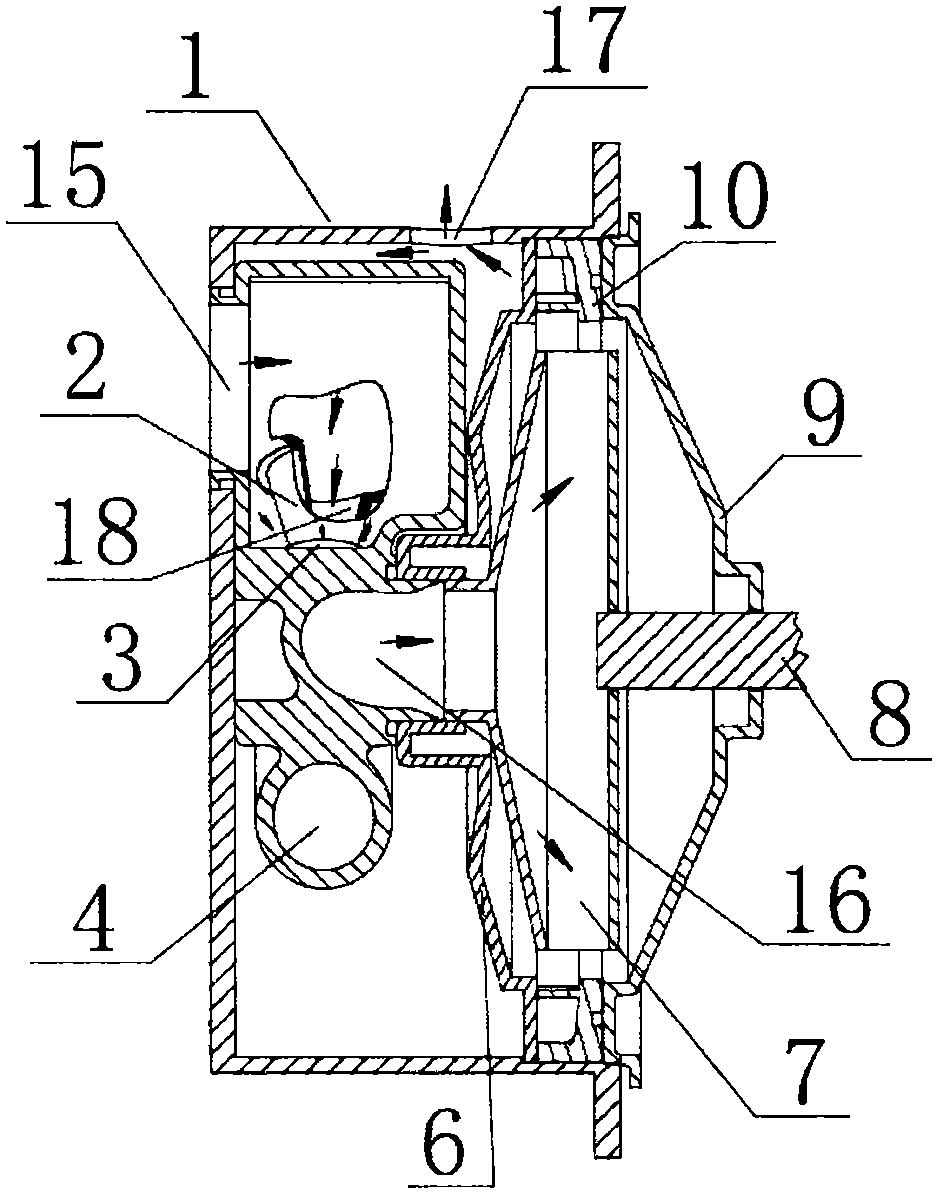
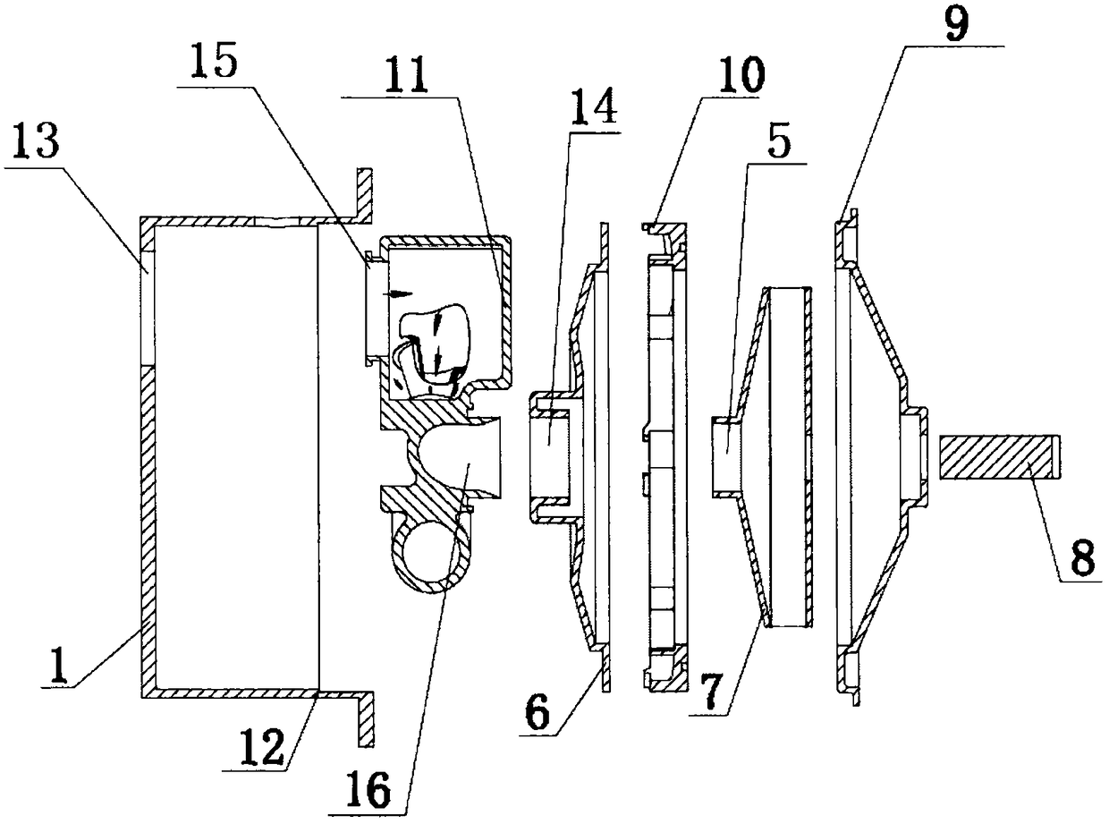
[0035] The structure of the high-efficiency energy-saving pump of the present invention is shown in Figure 1-Figure 5 shown. The pump body 1 is cylindrical with an opening 12 on one side, and a pump body inlet 13 is provided near the top of the pump body 1 . The opening 12 of the pump body 1 is sequentially equipped with a flow channel body 11, an inner swirl cover 6, a deflector plate 10 and an impeller 7 from the inside to the outside, and is fastened by the outer swirl cover 9 at the outermost end to form a whole.

[0036] A channel body inlet 15 is provided above the channel body 11 , which is engaged with the pump body inlet 13 . The flow channel body 11 is provided with a conical nozzle 2 with a large outside and a small inside. The other end of the spray pipe 3 is connected with a radial space mixing chamber 4 which is radially annular. The port of the mixing chamber 4 in the radial space is the outlet 16 of the mixing chamber, and the outlet 16 of the mixing chambe...


PUM


Abstract

The invention discloses an efficient energy saving pump. A runner body, an inner vortex cover, a guide disc and an impeller are mounted in an opening of a pump body in sequence from inside to outside,and are buckled as a whole by an outer vortex cover at the outermost end. A nozzle is arranged in the runner body, and is connected with a radial annular radial space mixing chamber through a spraying pipe. An impeller inlet in the center of the top end of the impeller is sleeved in an inner vortex cover inlet of the inner vortex cover for fixation through the guide disc. The center of the top end of the outer vortex cover is a shaft hole; and a rotating shaft is mounted in the shaft hole, is tightly matched with a center through hole on the impeller through the outer vortex cover, and is assembled with the impeller. The efficient energy saving pump reduces the energy loss, and achieves the effect of great supercharging compared with a common centrifugal pump.

Description

technical field [0001] The invention relates to a pump, in particular to a technical proposal of an energy-saving pump. Background technique [0002] Pump products are one of the important general-purpose mechanical products widely used in various fields of the national economy, and their annual power consumption reaches 18% to 22% of the national power generation. Generally, the pressurized water outlet of the jet pump impeller is radial, which is different from the axial water outlet of the nozzle, which leads to a large loss of energy of the liquid medium. At the same time, due to the different inlets of the two parts of the mixed liquid medium, the difference in the velocity vector results in a considerable part of the energy loss before entering the mixing chamber. Because the structure of the traditional jet pump body is fixed, it is difficult for one pump to generate multiple flow rates and the output ratio of the head, so it is difficult to realize the application o...

Claims


Application Information

Patent Timeline
IPC IPC(8): F04B23/14
CPCF04B23/14
Inventor 彭定泽徐培坚王胜
Owner 台州市禺工泵业科技有限公司
Why Eureka
Try Eureka