Pipeline sludge removing machine

A sludge and pipeline technology, applied in the field of pipeline sludge removal machines, can solve the problems of inability to achieve, cleaning and scraping, etc., to achieve the effect of improving efficiency, wide adaptability, and improving dredging and dredging.

Pending Publication Date: 2021-11-09
唐志奇
View PDF1 Cites 0 Cited by
  • Summary
  • Abstract
  • Description
  • Claims
  • Application Information

AI Technical Summary

Problems solved by technology

[0006] Aiming at the deficiencies of the prior art, the present invention provides a pipeline sludge removal machine, which solves the problem that the device cannot clean and scrape the sludge and impurities adhered to the inner wall of the pipeline when cleaning the sludge in the pipeline, and improves Improve the efficiency of sludge removal, thereby improving the overall effect of dredging and dredging, using water to wash and loosen the sediment on the inner wall of the pipeline, effectively cleaning and stripping the solidified sludge, achieving the purpose of recycling water flow, saving and efficiently use of water resources

Method used


Image

  • Pipeline sludge removing machine
  • Pipeline sludge removing machine
  • Pipeline sludge removing machine

Examples


Embodiment 1

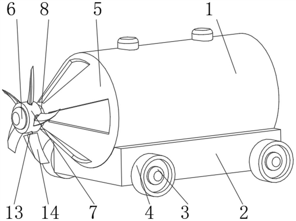
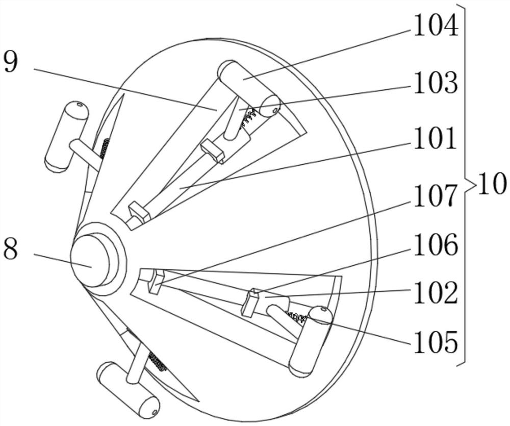
[0029] see Figure 1-3 , the present invention provides a technical solution: a pipeline sludge removal machine, including a housing 1, the bottom of the housing 1 is fixedly connected with a base 2, one side of the base 2 is symmetrically installed with a connecting shaft 3, and the end of the connecting shaft 3 is far away from the base 2 The moving wheel 4 is symmetrically connected, and one side of the shell 1 is rotatably connected with a conical shell 5, and the side of the conical shell 5 away from the shell 1 is equipped with a rotary motor 6, and the output end of the rotary motor 6 is rotatably connected with a rotary disc 7, and the rotating disc 7 is rotated. The side of the disk 7 away from the rotary motor 6 is fixedly connected with a connecting column 8, and the end of the connecting column 8 away from the rotating disk 7 is fixedly connected with the conical casing 5, and the outside of the conical casing 5 is uniformly provided with a device groove 9, and the ...

Embodiment 2

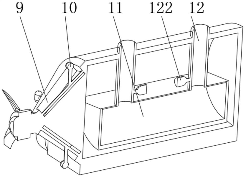
[0036] see Figure 1-5 , the present invention provides a technical solution: on the basis of Embodiment 1, a water storage frame 11 is installed inside the casing 1, and a water spray device 12 is evenly installed on one side of the water storage frame 11, and the water spray device 12 includes a water delivery pipe 121, one end of the water delivery pipe 121 communicates with the water storage frame 11, a water pump 122 is installed on the outside of the water delivery pipe 121 close to the water storage frame 11, and a semicircular arc plate is installed on the inner wall of the water delivery pipe 121 away from the water storage frame 11 123 , a water outlet 124 is evenly opened on one side of the semicircular arc plate 123 , and a water retaining plate 125 is slidably connected to the inner side of the semicircular arc plate 123 , and one side of the water retaining plate 125 runs through the water outlet 124 .

[0037] One side of semicircle arc plate 123 is provided wit...


PUM


Abstract

The invention discloses a pipeline sludge removing machine. The pipeline sludge removing machine comprises a shell; a base is fixedly connected to the bottom of the shell; connecting shafts are symmetrically mounted on one side of the base; moving wheels are symmetrically connected to the ends, far away from the base, of the connecting shafts; a conical shell is rotationally connected to one side of the shell; a rotating motor is mounted on the side, far away from the shell, of the conical shell; a rotating disc is rotationally connected to the output end of the rotating motor; a connecting column is fixedly connected to the side, far away from the rotating motor, of the rotating disc; the end, far away from the rotating disc, of the connecting column is fixedly connected with the conical shell; device grooves are evenly formed in the outer side of the conical shell; and a cleaning device is mounted in the device groove. The invention relates to the technical field of dredging. According to the pipeline sludge removing machine, the purpose of cleaning and scraping away sludge and impurities attached to the inner wall of a pipeline is achieved, the sludge removing efficiency is improved, and therefore, the overall dredging effect is improved.

Description

technical field [0001] The invention relates to the technical field of dredging, in particular to a pipeline sludge clearing machine. Background technique [0002] The urban drainage system is an engineering facility system that treats and discharges urban sewage and rainwater, and is an integral part of urban public facilities. Most of the drainage pipes in my country's cities are prone to blockage. The dredging of the pipes consumes a lot of manpower and material resources, and the work efficiency is very low. Therefore, there is an urgent need for a mechanical device that can replace manual labor to complete the pipe dredging work. [0003] For example Chinese patent CN112411734A proposes a kind of pipeline dredging robot, comprises: spiral wheel and car body; Car body comprises: swing arm, driven swing arm device, power supply, controller and active swing arm device; The frame of car body is made of aluminum The active swing arm device is installed on the front end of t...

Claims


Application Information

Patent Timeline
Patent Type & Authority Applications(China)
IPC IPC(8): F16L55/32F16L55/40B08B9/032B08B9/051B01D29/03B01D35/02
CPCF16L55/32F16L55/40B08B9/032B08B9/051B01D29/03B01D35/02F16L2101/12
Inventor 唐志奇
Owner 唐志奇
Why Eureka
Try Eureka