A self-powered pipeline monitoring device

A monitoring device and self-powered technology, which is applied in the pipeline system, gas/liquid distribution and storage, mechanical equipment, etc., can solve the problems of pipeline damage, high cost, oil leakage, etc., and achieve reliable working performance, high reliability, and signal detect sensitive effects

Active Publication Date: 2019-10-01
HANGZHOU DIANZI UNIV
View PDF7 Cites 0 Cited by
  • Summary
  • Abstract
  • Description
  • Claims
  • Application Information

AI Technical Summary

Problems solved by technology

[0002] Most of the existing pipeline monitoring devices are based on external power supply, and use strain gauges or other mechanisms to collect pipeline vibration data. This mechanism needs to be powered by power lines or batteries, and there will be some inaccessible areas such as remote oil pipelines. The cost of erecting remote power lines is high and requires frequent maintenance, while battery power requires regular battery replacement. Both solutions will bring high costs
There is also a self-powered pipeline monitoring device that needs to open a hole in the pipeline, and use the fluid in the pipeline to drive the slurry to rotate to generate electricity. Although this device solves the problem of power supply, the hole itself is a kind of damage to the pipeline, which is easy to cause Problems such as oil leakage have also brought many difficulties to equipment maintenance.

Method used


Image

  • A self-powered pipeline monitoring device
  • A self-powered pipeline monitoring device
  • A self-powered pipeline monitoring device

Examples


Embodiment Construction

[0027] The present invention will be further described below in conjunction with drawings and embodiments.

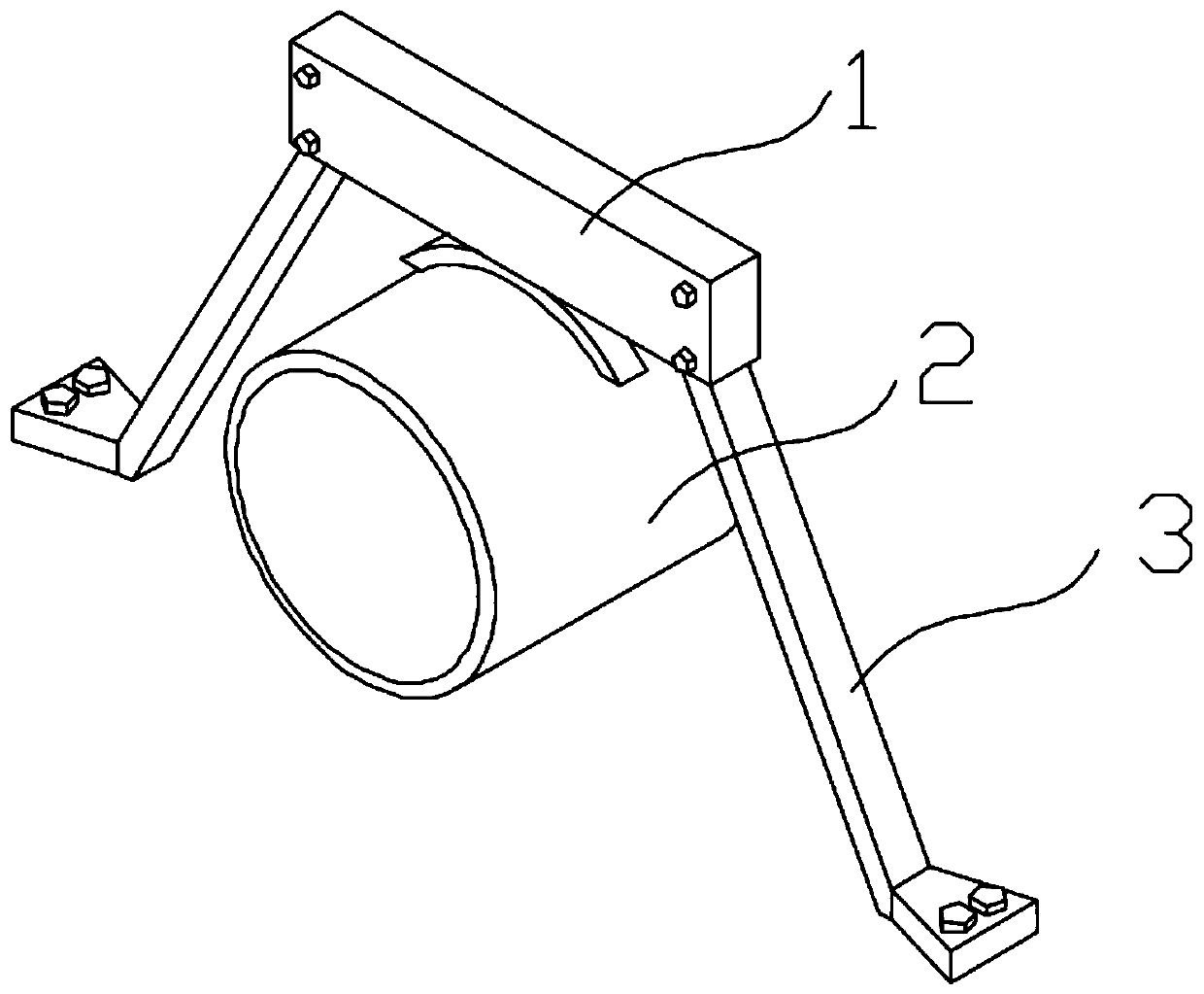
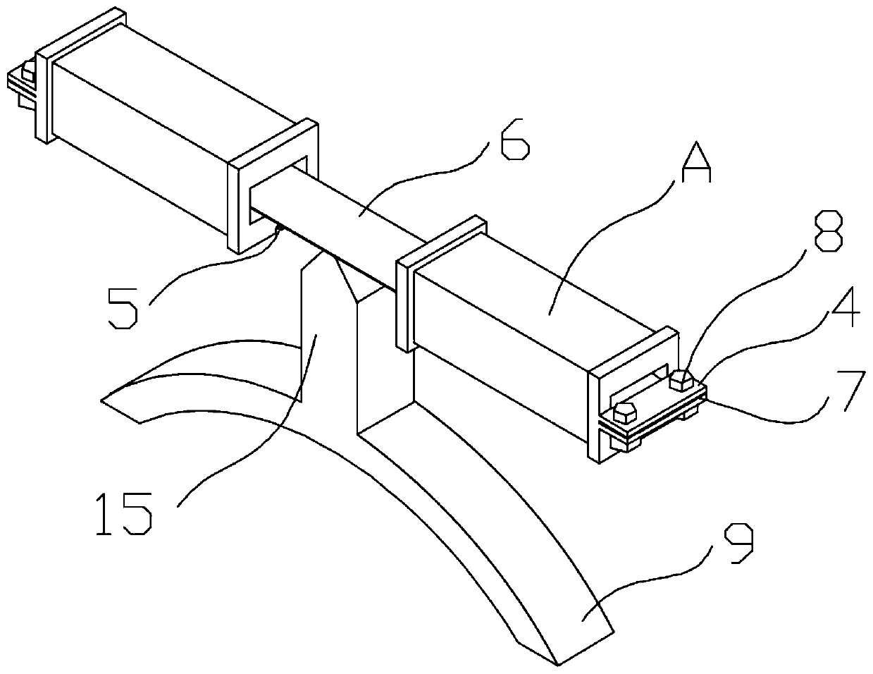
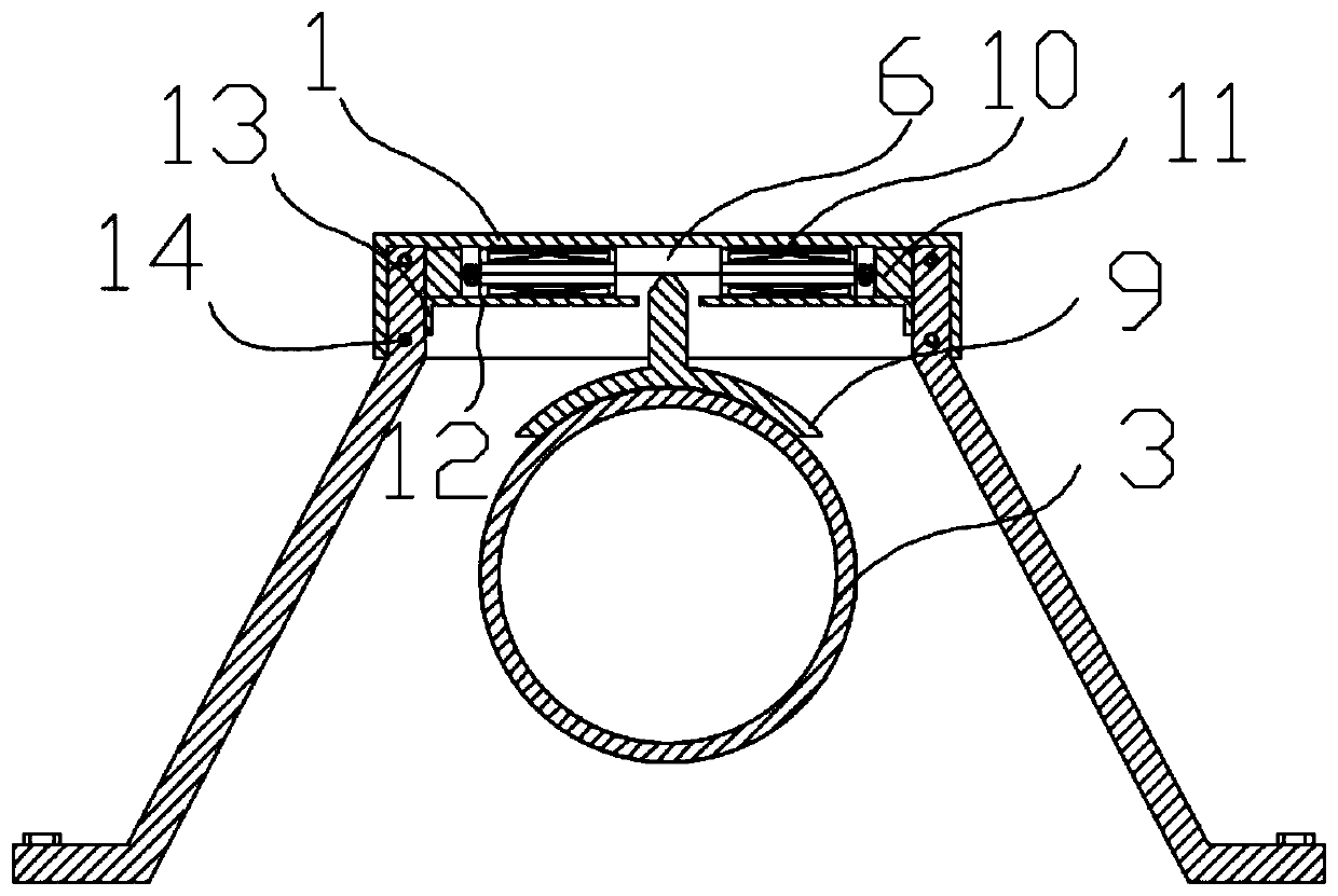
[0028] Such as figure 1 , 2 image 3 As shown, a self-powered pipeline monitoring device includes a fixed bracket 3, a magnetostrictive film 6, a bobbin 12, a bracket 13, a vibration transmission mechanism 9 and a coil 10, and the vibration transmission mechanism 9 is located above the pipeline 2, The top of the vibration conduction mechanism 9 is connected with the magnetostrictive film 6, and the fixed bracket 3 is located on both sides of the pipeline 2, and a bracket 13 is installed on the top of the two fixed brackets 3, and the bracket 13 is equipped with Place the coil bobbin 12, the inside of the coil bobbin 12 is provided with a cavity, the two ends of the magnetostrictive film 6 pass through the cavity of the coil bobbin 12 and are connected to the outer end 4 of the coil bobbin 12, the outer end of the coil bobbin 12 An annular groove is provided on the su...


PUM


Abstract

The invention discloses a self-powered pipeline monitoring device, which comprises a fixed bracket, a magnetostrictive film, a coil frame, a bracket, a vibration transmission mechanism and a coil. The upper part of the fixed bracket is equipped with a bracket, and the coil frame is placed on the bracket. The two ends of the magnetostrictive film pass through the cavity of the coil frame and are connected to the outer end of the coil frame. In the slot, a permanent magnet is arranged between the outer end of the coil frame and the fixing bracket. The invention has two independent coils, one coil is used for the energy storage circuit to supply power to the external circuit, and the other coil is used to detect the vibration of the pipeline and record it for the external circuit, which can collect the electric energy generated in the pipeline vibration process to realize self-power supply, and can Monitoring of pipeline vibration.

Description

technical field [0001] The invention belongs to the technical field of pipeline monitoring and relates to a self-powered pipeline monitoring device based on magnetostrictive materials. Background technique [0002] Most of the existing pipeline monitoring devices are based on external power supply, and use strain gauges or other mechanisms to collect pipeline vibration data. This mechanism needs to be powered by power lines or batteries, and there will be some inaccessible areas such as remote oil pipelines. Long-distance transmission lines are expensive and require frequent maintenance, while battery power requires regular replacement of batteries. Both solutions will bring high costs. There is also a self-powered pipeline monitoring device that needs to open a hole in the pipeline, and use the fluid in the pipeline to drive the slurry to rotate to generate electricity. Although this device solves the problem of power supply, the hole itself is a kind of damage to the pipel...

Claims


Application Information

Patent Timeline
Patent Type & Authority Patents(China)
IPC IPC(8): F17D5/06
Inventor 孟爱华潘文武张梅严纯
Owner HANGZHOU DIANZI UNIV
Why Eureka
Try Eureka